Altair8800c
Running Altair BASIC VER 1.0 brought my interests back to the beginning of the microcomputer era. My stripped-down IMSAI 8080 served as a means to try loading the proto-Microsoft BASIC from paper tape. I enjoy running the IMSAI, but I've built it up to a configuration that feels more like a later 70s CP/M machine, with its two clacking 8-inch disk drives and ADM-3A terminal. Early MITS BASIC would be better on a simply configured Altair 8800! A machine with a little RAM and a serial card attached to the Teletype, just like Paul Allen would have encountered on his first trip to Albuquerque in 1975.
I have enough old stuff, though. I own a handful of period machines from the early development of microcomputers. This collection represents my own early experiences with computers (Apple II+, TRS-80 Model III, Apple //c, Apple IIe, VIC-20, Commodore 64), machines that reflect an interest in the rapid evolution of the industry (Processor Technology Sol-20), as well as other curiosities of that age (Osborne 1 and 1A). I'm not that interested in acquiring more vintage gear. Altairs tend to be pricey, too.
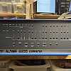
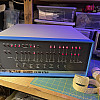
An alternative is the Altair 8800c. The Altair 8800c is a project envisioned by Mike Douglas -- a reproduction case, front panel board (blinkenlights and switches), and novel front panel interface card. (See his site here.) It's a sweet mashup of old and new -- a fully functioning S-100 (Altair) bus machine with contemporary takes on a few of the parts; notably, eliminating the wiring harness from the front panel to the backplane with an elegant 50-conductor ribbon cable and interface card and, of course, modern switching power supplies.
Getting an Altair 8800c was an opportunity to actually build an early microcomputer from scratch, just like those first MITS mail-order customers, using the same tools and materials -- soldering up DIP ICs and components into through-hole PCBs. The experience is an exercise in practicing kit-building craft and skill, and, of course, troubleshooting. Maybe I should have gone all the way and camped out in Albuquerque when I built it, like Steve Dompier.
Building the kit
Getting started
Mike's kit included a reproduction case and dress panel, front panel display board, and front panel interface board. He sold the front panel board with the toggle switches. The rest is up to the builder: sourcing a backplane, the power supplies, CPU card, and other Altair bus cards. From what I've seen, many Altair 8800c builders use a replica MITS CPU board and then add modern S-100 cards (cards designed recently by hobbyists) to provide ROM, disk interface, serial communications, and memory. My goal was simpler. I sourced a modern 9-slot backplane and the bare CPU board. I also built a homebrew serial board that mimics the MITS 88-SIO REV 0 (with REV 1 modifications) -- more on that later.
The display board, front panel interface, CPU card, and power supplies all required orders from parts suppliers. The TTL ICs, processor, crystal, capacitors, resistors are still readily available as new or new old stock. I had a number of TTL parts in my bin, and I used a few of those -- although I frequently order spares in case I have a bad component. Some replica builders focus on sourcing period-correct parts. My interest was more on getting a working system up and running. Again, the blend of old and new is more interesting to me, especially since the machine isn't an exact replica of the 1975 Altair 8800.
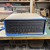
Above: The Altair 8800c case.
Front panel board
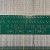
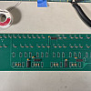
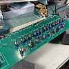
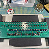
After most of the parts arrived, I began by building the front panel board. This was fairly straightforward, but required a few tricks to get the switches and LEDs in a good arrangement. I wish I took more photos of the techniques. One basically uses the front panel to align and hold the switches, and then mounts the PCB on top. It's a giggly mess as the switches move around, but then a rush when they all fit in the PCB holes. It's unbalanced, though, so there's a tendency to lose the fit. With a little fidgeting, one gets a sense of where to hold the PCB. It all becomes more stable as the switches are soldered in.
The LEDs present another interesting challenge. One places the LEDs in the PCB, then mounts the dress panel on top. The LEDs are pushed into the dress panel. My LEDs were small enough to fit into the holes. The result are LEDs that sit quite a way off the board. I left the remainder of the LED leads on until I was sure that they were aligned well. The rest of of the front panel is completed by just soldering in the few logic ICs, capacitors, and resistors.
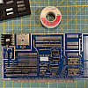
Above: Assembly steps for the front panel board and the assembled panel installed in the Altair 8800c case.
Power supplies
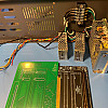
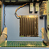
Next up was power. Three small switching supplies provide the +8, +16, and -16VDC rails. These are roughly at the specs of the historic Altair 8800 PSU, albeit regulated and without the heavy transformers. They're actually +7.5, -7.5, and 15V, but a loaded unregulated power supply was probably around that, anyway. Selecting, wiring, and installing the power supplies is completely up to the builder. I chose to bring in the AC power to a terminal block. The neutral and ground wires pass through to the power supplies, while line is routed to the front panel power switch and back to the terminal. The PSU outputs connect by a harness with a molex connector to the motherboard. Once the power supplies were wired and checked (I eventually redid all of the wiring to clean it up), I planned the layout and drilled seven M4-sized holes to mount them to the base. I wish I had a more precise way to do this other than a hand drill, but it worked out in the end. I positioned the power supplies to give clearance for installed cards in the motherboard and for a fan. As a result, there's a lot of empty space on the left side of the case. The motherboard powered on without issues, confirming that the supplies were set up correctly. There were some nice crafting details here that I enjoyed: soldering the wire terminals properly, including heat-shrink tubing. Only one thing bothers me: the power cable came out of the strain relief. I'll have to fix that, eventually.
Above: Arranging the wired power supplies. The installed power supplies and backplane before and after a smoke test.
Backplane
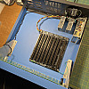
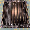
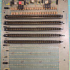
I'm using a modern 9-slot backplane with 100-pin slot connectors taken from an old, fairly borken Godbout motherboard. Desoldering eleven 100-pin connectors and soldering up nine of them on the new board was an act of mindful meditation. The finished backplane has a pleasant, compact heftiness. The motherboard can be built for active termination. I skipped that and I also wired the optional fuses as jumpers. The power supplies should shut down quickly in the event of a short.
Above: A modern 9-slot backplane and the donor vintage Godbout backplane.
Front panel interface board
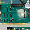
This interface board replaces the wiring harness from the front panel directly into the backplane in the original Altair 8800 -- a tedious and error-prone design that is a frequent source of failure in the original machines. MITS' later Altair 8800b incorporated an interface similar to the one Mike designed. The front panel connects to the interface board by a standard 50-conductor ribbon cable. The 8800c's interface board also includes a microcontroller that adds a few alternative functions. One them is a slow-stepper -- holding down the single step toggle switch, steps continuously at an adjustable rate between 1 and 8Hz. The microcontroller can also inject code into memory, such as common boot loaders and even a few short programs, like Kill the Bit, and there are echo routines to test the serial connection. It's a handy and cool feature -- an Altair Easter egg in a way. Soldering it up was straightforward.
Above: The front panel interface board before and after assembly.
MITS CPU-80
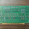
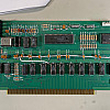
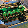
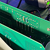
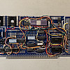
Finally -- the MITS CPU board. This is the card that started everything! The traces are so alien with their sharp corners. The CPU sits in the upper middle of the board, with the clock generator to its left and the 8212 interface to the data bus to its right. Most of the rest of the card are just 8T97 buffers that connect the 8080 processor directly to the bus. There's not much to it! The board took longer than I expected to assemble, partly because I had to make multiple orders of several parts that I forgot in previous orders, including the wafer connector in the top right and Q1, a transistor that controls the power-on clear (POC*) signal. I wonder how many hobbyists built this board only to install the microprocessor the wrong way? (Its correct orientation is upside down on the board). The other conspicuous features are the five jumper wires. Stuff that in your pick-and-place machine!
Above: The replica MITS CPU board before and after assembly.
Smoke test and debugging
All set! Cards installed... pressed down firmly in those slots... power supply plugged in the motherboard... ribbon cables in the correct orientation... voltages checking out... double checking everything... power... ON
Did it work right away?
Yes!
Sort of!
The machine powered up, but it was unresponsive. Play a sad trombone note! Still, there were no flames, audible pops, or releases of magic blue smoke. And, after about three minutes, some function came unexpectedly to the front panel -- data lights started to show the memory and I could toggle to different addresses intermittently. The examine next and deposit next toggles sometimes worked, but often would stop off of the M1 cycle or go to a random address. After a few more minutes, everything locked-in and the machine worked fine. I powered it up on different days and got the same result. So, there were a few bugs to work out.
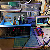
Scoping the clock generator (phi2, IC Q pin 5 and phi1, IC Q pin 13), I could see that the clock wasn't starting when the machine was first powered on. After some time, the clock started, but exhibited a toggling behavior -- turning on and off -- around 500kHz. Finally, the clock would become steady. Now, it's known that the MITS CPU card clock usually needs some adjustment. I'm not sure if this happened for original Altairs, but most modern builds require adjusting R41 and R42, which set the duty ratio of the phi1 and phi2 clocks and their separation. But the machine eventually worked, so it seemed more like a power issue. The 5V regulator did read a little low -- 4.86V -- but that's not too far off. However, it was entirely out of spec during startup. The regulator powered on to only about 3.5V.
I replaced the Motorola MC7805CP (date code 7702, it looked so good with the gold pins!) with a slightly newer and far less appealing LM340T5. Now the 5V rail came up right away. The issue then was that the machine just wouldn't work. The fix, of course, was tuning R41 and R42. There was only about 48ns between the fall of phi2 and the rise of phi1. Apparently, the minimum spec is 70ns with a minimum high time of 220ns for phi2 and 70ns for phi1. I decreased R41 and R42 by bodging two resistors to the back of the board in parallel, getting the resistance across R41 to 9.8k and across R42 to 5.3k. The measured phi2 high time was now 245ns, phi1 was 104ns, and I had a separation between the fall of phi2 and rise of phi1 of 110ns -- all comfortably larger than the minimum values. Why did the clock work with the (presumably) weaker regulator after "warming up"? Beats me!
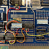
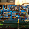
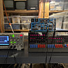
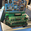
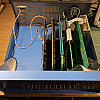
Above: (left) A minimal Altair 8800c configuration: CPU, front panel, and memory. (center) Two bodge resistors tuning the value of R41 and R42 on the CPU card to bring the system clock into spec. (right) Measuring the phi1 and phi2 clock pulses.
Up and running
The minimum configuration of an Altair is the CPU card and memory. The original shipped with just 256 bytes of RAM. That's more than enough if you're toggling in programs into the front panel. Steve Dompier's Music of a Sort is just over 200 bytes. I've toggled it in. You only have to do that once (unless someone trips over the power cord).
I performed my initial tests using a Processor Technology 4K static RAM board, the company's first product. It came before their successful video board (VDM-1) and well before the Sol-20 microcomputer. The Proc Tech 4K board started the company! It was among the successful products in the cottage industry of RAM cards that served the burgeoning Altair user community, thanks to the abysmal performance of the MITS offerings. [1] On a recent online discussion, one user writes of their experience with the MITS memory: [2]
Despite the machine's limitations in a minimal configuration, a compelling program to toggle in is Kill the Bit, the 24-byte game written by Dean McDaniel. It is pretty entertaining. The game starts with a traveling bit -- the LED lights up above the eight upper address switches, traveling steadily from left to right. Toggling a switch on and off just as the bit passes over it will turn the light off. But if you're too fast or slow and you miss "hitting" the bit at the right moment, another light toggles on and travels with the first. Now there are two bits to kill. The game continues this way -- success leading to fewer lights, failure causing more to light up and travel along the LEDs. I never felt comfortable playing it on my IMSAI due to the wear (or worse) on the switches and paddles that could result, but here on this brand new old machine, I'm less timid about hitting the switches a little hard. 24 bytes of fun! Load that in your Steam Deck and smoke it!
Once you get tired of killing the bit, it's entertaining to make alternating light patterns with the program. Running it also made me realize that the Altair lacks a way of displaying the 8080's programmed output to port FF, which the IMSAI can generate on a separate bank of LEDs. Finally, toggling in a 303 000 000, a jump instruction to itself, is a neat way to demonstrate the instruction fetch and data cycles while single stepping the processor. Want to see a Von Neumann architecture? Here you go!
4K is significantly more RAM than anyone would toggle a program into, so the next step is to get the machine communicating with a terminal and storage of some kind. Spoiler: the terminal is a Teletype and the storage is paper tape.
Above: (left) The Processor Technology 4K static RAM board. (right) Playing Kill the Bit.
SSM IO-2
An excuse to confuse myself between DTE and DCE. Again. Or: Just keep adding null modems until it works.
For serial communications, I needed 110 baud and something that would run like an early MITS 88-SIO, the first serial card offered for the Altair. Existing copies of Altair BASIC version 1.0 rely on the I/O port definitions used by the earliest 88-SIO card, "REV 0". It's easy to patch the I/O routines, but I wanted to run the 8800c in this earliest configuration. While I could wire my Processor Technology 3P+S card to act like an MITS interface, I decided that the early-hobbyist thing to do would be to build a 110 baud interface from scratch. (I also use the 3P+S card as a console in my IMSAI. I didn't want it doing double duty.) So, I used a replica of an early board from Solid State Music -- the IO-2 board -- which can be built to (simultaneously) operate like the 88-SIO REV 0 and REV 1 interface cards.
A little background: (for reasons that I don't understand) MITS changed the 88-SIO card to use different status byte words. Confusing matters, MITS released a second dual-channel serial card shortly afterward, the 88-2SIO, that changed them again. These differences seem to be related to handshaking or (perhaps never fully realized) interrupt handling designs. By default, the 88-SIO uses the 8080 I/O port 0 for the status word and port 1 for data, while the 88-2SIO (channel A) uses ports 10h and 11h for status and data, respectively. Below is a table that summarizes the status words of the REV 0, REV 1, and 2SIO cards.
| REV 0 | REV 1 | 2SIO | |
|---|---|---|---|
| status port | 00 | 00 | 10 |
| data port | 01 | 01 | 11 |
| status word | |||
| D7 | TBE* | ||
| D6 | |||
| D5 | RDA | ||
| D4 | |||
| D3 | |||
| D2 | |||
| D1 | TBE | TBE | |
| D0 | RDA* | RDA |
Table: ports and status words for three MITS serial boards. An asterisk indicates an active low signal.
In the table, RDA refers to the status of the UART input data buffer (Read Data Available), and TBE refers to the output buffer (Transmit Buffer Empty). Here, I'm ignoring other status bits that might be available, such as those that indicate frame or parity errors. For the 88-SIO REV 0, a byte is available to be read in when the status word bit D5 is high. Likewise, the transmit buffer is available to send a character when D1 is high. Here's a snippet of code from Altair BASIC Version 1 that shows the output character routine. To send a character, the routine keeps checking until the transmit buffer is empty. When it's clear, it sends the byte through the I/O data port to the UART.
01A8	F5 		PUSH PSW
01A9	DB 10 		IN 0h		; get status byte
	E6 02		ANI 02h		; check TBE
	CA A9 01	JZ 01A9h	; not ready, loop back
	F1		POP PSW
	D3 11 		OUT 01h		; send byte
	C9		RET
Unlike REV 0, the REV 1 board uses status bits D0 and D7, although they are active when low. One benefit of the REV 1 arrangement is that the status word bits can be checked with simple rotate left with carry (rlc) or rotate right with carry (rrc) instructions, followed by a conditional jump or return if the carry bit is clear. Other routines like the one above will use a logic AND to test the status word with the appropriate mask (e.g. ANI 02h or ANI 40h) and then perform the appropriate conditional branch, usually JZ or JNZ.
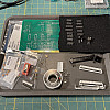
Building the serial board was a fun side-project. The (nearly) finished card is shown below with point-to-point soldered wires connecting the baud rate generator, General Instruments AY-5-1013 UART, 8212 buffers to the bus, and RS-232 drivers and receivers. The AY-5-1013 uses two voltages (+5 and -12 V) and the 1489 EIA driver requires +12 V, so there are three regulators on the board. The SSM IO-2 is a clever and useful prototyping board that provides the basic circuits for power, I/O port addressing, and interfacing with the data bus. The pictures below also show it being tested in the IMSAI and, later, the Altair.
Building the SSM-IO2 serial card.
Testing the card in an IMSAI 8080 and Altair 8800c.
More memory
Restoring a Digital Research 16K RAM card
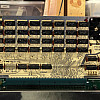
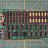
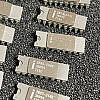
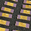
4K is a little too lean for running MITS BASIC. Moreover, I want to eventually play around with 8K versions that were released alongside of the 4K offerings back in 1975 and 1976. Plus, the original MITS BASIC Version 1 takes a little more than 4K -- it was optimized significantly by Allen and Gates in the year after they teamed up with Ed Roberts. I started designing a simple RAM board that I could possibly build up with a protoboard somewhere in my storage bin. Unfortunately, that board is designed for wire wrapping. But while I was rummaging, I stumbled across a 16K RAM board -- part of an acquisition when I bought my first teleprinter, the Olivetti Te-318. I don't have that much gear, but I had forgotten about this card. I had little hope for it, though. It was crusted with dust and dirt and many of the RAM chips (beautiful, gold-plated purple ceramic and black ceramic ICs) were beat up.
The board is a static RAM card offered by Digital Research. -- not Gary Kildall's Digital Research of CP/M fame, but a completely different firm in Dallas, Texas. The board uses 2114 RAM, which is 1K of 4-bit words -- combining eight together provides 4K of RAM. There are four banks of the chips to give a total of 16K. The other odd feature of the card was that it substituted an LM323K power regulator for three separate 7805 regulators. This setup is similar to a Seals 32K RAM card that I own, and it is the potential source of problems due to possibly overheating. It has a beefy heat sink and a liberal amount of 1970s-era thermal paste.
Before powering it up, I removed all of the ICs from the board and cleaned it. Notice that all but two of the ICs are ceramic. Many of the ICs of course had oxide buildup on their legs, which I cleaned off. One of the ICs had enough corrosion that a leg fell off -- not uncommon for vintage ICs. I soldered a short wire to the pin.
The next step was powering the board up without the ICs to check the regulators. I was worried about several tantalum capacitors on the board. I checked them for shorts, then I put the card in the Altair (using a riser card, which has the added benefit of fuses on the power lines). I donned my safety classes, counted down, and hit the power. All was good. The regulators functioned fine, and the tantalums didn't explode.
I added the ICs back and powered up the card again. I was surprised that it worked the first time, with no bad bits at all. I ran memory checks on it for a while by adapting the memory check that Mike included on the 8800c PIC. The program allows you to input a range of memory through a terminal. It's set up for the 2-SIO, though, so I have to patch a few bytes for it to work with my 88-SIO "clone". At first there were some intermittent issues, but these were likely due to weak connections in the old slots that I used for the backplane. Since then, it's been operating well, without any problems, except for thermally shutting down once. The addressing scheme is pretty flexible, too. Each of its 4K blocks can be addressed separately by wiring a jumper. These jumpers were hard-wired to the second bank of 16K. I desoldered the jumpers and installed machine pins and an IC socket so the board addresses can be changed quickly. The board is currently addressed at 1000-4FFFh, above the 4K Processor Tech RAM card.
20K! More than enough for where I'm headed.
One interesting observation running both of these cards: I've had to turn off memory protect each time I started the Altair. The Processor Tech RAM card has a memory protect feature, which is enabled by default when the machine powers up, but the Digital Research card does not. When I'm addressing the 16K board, the memory protect light will turn off on the front panel, and it will turn back on when the Processor Tech board is addressed.
Above: The Digital Research 16K RAM board and the ceramic 2114 memory ICs it came with.
Running MITS BASIC
MITS BASIC Version 4.0 loaded from punch tape.
I wanted to take a shot at running a slightly later version of Altair 4K BASIC, since I've already tried Version 1 on the IMSAI. How much did Gates and Allen improve their BASIC the span of a year? A lot, it turns out! Loading later versions is quite a bit different, too. The toggled-in boot loader starts by reading a second stage loader from the punch tape. [3] It loads it from the top of memory down, so the byte order is reversed on the tape. Sense switches (the upper 8 address switches) are used to select the serial board and version (4K, 8K, or extended 12K). It's neat to watch the program switch over to the second stage boot loader. The light pattern changes, and there's a hint of activity in the blinking that provides some sense of its progress. A short six or so minutes later, the Teletype comes alive with the MEMEORY SIZE message, followed by a query for the number of columns (default 72) and whether you want the sine function (or other trigonometric functions).
17100 glorious bytes FREE! And that's free as in freedom.
I tested it with Paul Allen's PRINT 2+2, a quick run of Hellorld, and a not-so-quick go at an ASCII Mandelbrot. This hacked benchmarking test demonstrated that the floating point routines had sped up significantly between versions 1 and 4. I was able to do more than double the number of iterations on the Mandelbrot than in Version 1 BASIC. Surprisingly, the number formatting scheme still prevented me from printing the "colormap" Mandelbrots. I had to stick with the simpler asterisk that shows the extent of the set.
Another thing that worked now, too, was reading a program listing back in from punch tape. I was able to save and read the Mandelbrot program, which should save me some (re)typing in the future. [4]
Next up is probably running 8K BASIC. I have to punch a copy and then find the time to load it in (about 14 minutes on the Teletype). Hand winding the paper tape sounds like fun.
Above: The first run of 4K BASIC Version 4, an example of an ASCII Mandelbrot with the punch tape program, and the Altair 8800c.
Even cooler!
Running BASIC with the case enclosed ended up causing the 16K RAM card to shut down, which lead to the machine locking up. I powered down the Altair and everything worked with the 16K board removed. Once it cooled off, I tried again and it ran fine. The situation wasn't unexpected. The 16K RAM board uses both 7805 and LM323K regulators. The latter handles a load that would normally be distributed between three 7805s. I had the same problem with a similar regulator on my Seals 32K RAM board. Static RAM draws more current than dynamic RAM. This board probably uses (and needs to dissipate) on the order of 20 or 30W, most of which ends up as heat. Unless I wanted to run the machine with the case off, it looked like I would need to install a fan.
I picked up an inexpensive 12VDC 120mm case fan and an adjustable DC-DC buck converter to step down the 16V (15V) power. I wired the fan to the converter, adjusted the voltages, and hot glued the converter to the lower edge of the fan. I ran the power wires from the converter to the motherboard, where I installed two jumper pins to 15V and ground. I'm reasonably satisfied with the installation, and it seems to be keeping things cooler now with the case lid on.
Notes and references
- Manes' biography of Gates has some good details about the MITS DRAM boards and MITS economics at the time (chapters 5 and 6). The RAM cards were an important money maker for MITS -- the Altair was sold nearly at cost! But the flakiness of the boards contributed to a lot of resentment among customers, including not paying for BASIC according to some. Trying to save sales, Ed Roberts argued that DRAM was necessary for power efficiency compared to SRAM (the original Altair PSU being somewhat light, p. 85). Meanwhile, Processor Tech, Godbout, Solid State Music, and yes, Parasitic Engineering, were eating MITS lunch selling 4K and 8K static boards. The latter company's name was chosen in response to Ed Robert's views that these upstarts were all MITS parasites.
- Vintage Computer Forums. https://forum.vcfed.org/index.php?threads/did-the-mits-altair-4k-board-not-work-back-in-the-day.1246828/post-1366900. Retrieved February 26, 2024.
- This is the current 20-byte loader that I'm using for 4K BASIC Version 4:
041 302 017 061 022 000 333 000 017 330 333 001 275 310 055 167 300 351 003 000, which is toggled in beginning at address 0, which is for the 88-SIO serial interface. Sense switches A13 and A9 should be on when the loader is run. This signals the second stage loader that the 88-SIO interface is being used on ports 00 and 01. The switch settings and loaders are documented in the MITS Altair 8800 BASIC reference manual from 1977. (The loader is also an Altair 8800c easter egg: set address 016 and depress AUX-Left to inject this code snippet into memory.) The same loader can be used for 8K BASIC Version 4 by changing the third byte of the loader from017to037. (The 8K code snippet is loaded by setting address022.) - Method for saving to tape (as documented in the 1975 MITS Altair BASIC manual on page 43): [5]
- Type the command
LISTwithout pressing RETURN - With the TTY reperforator off, place the machine in LOCAL mode
- Turn on the reperforator
- Simultaneously press the REPEAT-SHIFT-CONTROL-P keys to punch a leader of NULLs
- Turn off the reperforator, and return the machine to LINE mode
- Turn on the reperforator and press RETURN to generate the listing
- Turn off the reperforator, place the machine in LOCAL mode
- Turn on the reperforator
- Simultaneously press the REPEAT-SHIFT-CONTROL-P keys to punch a trailer of nulls
- Again turn off the reperforator, and return the machine to LINE mode
- Type the command

