A welcome surprise
One of the boards that came with my machine was this Seals Electronics memory card. This card is a beast. It's packed to the gills and sits about a half an inch higher than the other cards in the chassis.
It didn't work at all, so I shelved it while I plugged away at getting the IMSAI running. I hadn't taken a close look, and I just assumed it was some variation of their prolific 8K SRAM board. When I finally got around to it recently, I started by looking up the part numbers—Texas Instruments TMS4044. Hmm... 18 pin, 1bit x 4K... 64 chips... this is a 32K board!
It's interesting to see how those extra two pins for each memory chip make a difference in the layout. With an extra eighth of an inch or so for each 4044 and eight columns, that's an inch more over the 8K 2102 boards. Squeezing everything on was quite a feat for the designer.
Searching for information or ads on this Seals board has not yielded much. The 8KS SRAM board manual is available online, but I've only seen scant references in the old journals to the 32KS board, mostly in quarter page ads of mail-order retailers. I'm guessing that the board was a short run between the popular 8K board and the 64K SRAM card that was sold around the same time Seals came out with their own S-100 system, the PUP-1. The silkscreen copyright is 1978 and all of the TMS4044 chips have date codes of 7810. Based on a letter to the editor in 68 Micro Journal Volume 2, Number 9, Seals went bankrupt somewhere between 1979 and 1980, so the 32KS comes relatively late in their history.
Without a manual or schematics the board is a pretty good puzzle. One unusual feature that jumps out is the single high current 78H05K regulator and big ole heat sink. Many S-100 memory boards distribute the load of the numerous SRAM chips with several 7805 regulators, each topping out at 1.5A or so. The designer's choice of the single regulator is clear now—with the larger 4044's there was nowhere left to fit four normal 7805 packages. The 78H05 should work up to 5A with sufficient heat dissipation. This was the first problem—the regulator wasn't holding anywhere near 5V. Its output was about 1.3V. So that was the leading symptom of the board's borkenly behavior.
I started looking for shorts, but nothing was immediately obvious. I pulled the tantalum caps. These checked out at about 6.8 microF, consistent with their labeled ratings. Next, I pulled the 78H05K. Under a light load, it did fine delivering 5V from a 12V power supply. I ordered a replacement LM78H05K, but it heated up and failed without ever generating 5V. It was stuck around 2V or so and it generated much more heat, so I reinstalled the old 78H05K. With a somewhat cooler temperature in the retrobunker, it held for about a minute at 5V before shutting down. A real enigma. Could it be a short in a part somewhere? I pulled all of the chips with the thought that I'd rebuild this sucker and see if it gets somewhere.
Rebuilding the Seals Electronics 32KS
Powering on without any chips, the regulator held steady at 5V and the total power consumption of the computer was 30W, the same as the computer without the memory board (just the front panel and processor card.) Next, I added back all non-memory control chips. The power draw was now 34W. Several chips were warmer, with chip 74 much warmer. This is a Texas Instruments 74S287 PROM (another mystery). The 78H05 was nice and cool.
Row by row, I added back the 4044 SRAM. I first put in the top row. The regulator held steady (but was much warmer), and was able to deposit memory at $8000, $8400, $8800, $8C00 and $8F00. Bit 4 was stuck high. (Bits are 0 on left of a row, 7 on right.) Next, I replaced the bottom row (chips 57-64). The computer was drawing about 40W, and memory starting at $7000 was active, with all bits good. The second row up from the bottom (chips 49-56) gave memory starting at $6000. The power draw was now at 44W. 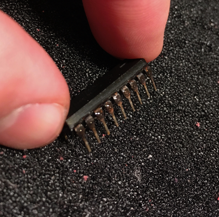
Each time I replaced a row, I cleaned the chip pins with deoxit and a rubber eraser. The pins of the 4044's were heavily tarnished and many had a pretty thick oxide buildup. Three pins had to be resoldered or repaired due to the strain of pulling them out of their sockets (even doing so slowly and carefully.)
At this point, I put an ammeter into my riser board 8V power line. With three rows of RAM in lower bank and one row of RAM in top row (half of the SRAM back in), the measured current was steady at 1.67A with the processor in a WAIT state. The computer was at about 45W. Running a short test program (like C3 00 00) the current draw was 1.71A. I could measure the current this way until all of the chips were back in. At that point, the overall power draw by the computer was 62W (about 32W attributed to the 32KS.) The Seals board current draw measured about 2.5-3.0A, but the lead wires I used to the ammeter ended up smoking. Guess I should've used a lower gauge.
Surprisingly, the regulator held up with the fully repopulated board. Why? Maybe cleaning the leads on the chips helped? The retrobunker has been quite a bit cooler these days, too (about 66F). I ran it for about 15 minutes without a problem.
With a fully populated board, I have 32K of memory at addresses $4000-$BFFF (minus the sticky bit 7 on the last 4K bank. I'll need a replacement TMS4044.—Edit: MM5257 obtained and installed.) The top 4 rows of 4044's correspond to a 16K bank, starting at $8000. The bottom four rows are the lower 16K bank, starting at $4000. I have no idea what the DIP switch settings should be. They were originally set to "1101 0010," labeled LLD and ULD, respectively. Presumably the DIP settings determine the memory range, but the mapping isn't clear. At one point, $4000-4FFF stopped working. I discovered that I had bumped the first dip switch to "0".
My next step is to see if the board can be operated reliably or whether I still have to replace the 78H05K. I have a switching regulator replacement I can try. I want to experiment with the DIP settings to see if I can change the address space. What is the purpose of the PROM?
On the other hand, the board covers a memory range that complements my two other 8K boards. With 48K, I'm suddenly launched within the realm of running CP/M. What an unexpected and delightful development.
Working on a few memory boards has me wondering about the failure of these early SRAM chips. The 8K IMS board I have had about a dozen or so 2102 chips that had failed, while the Solid State Music board only had one or two. Maybe the storage conditions of the IMS board were harsher. The Seals board was stored with it and the tarnishing and oxidation on the 4044 chips the worst I've seen. Yet, out of the 64 chips on the Seals, only one was borked. Is there a correlation with date code or batch or manufacturer? The IMS 2102's were National Semiconductor parts, mostly from mid 1977. The SSM's were NEC with lot number K69085. Others note the potential failure due to overvoltage and heating. Maybe the IMS board just saw more service under tougher conditions?
My other mystery is why the 78H05K is now working on the Seals board. Was it just cleaning up the chips that solved this problem? I'm guessing that running it with the serial and two other memory boards installed also helps by dragging down the 8V line on the backplane, which means less heat has to be dissipated by the regulator. I'll have to make some measurements to confirm.
Follow up—addressing the 32KS
I was curious about the addressing logic of this board and how to change the address range. The board had to detect the upper address lines, at least A12-A15, and possibly down to A10. Starting from A15, I traced the signal through a 74LS244 buffer (IC 76, in on 17, out on 3) to three chips: 68 (a 74LS138 decoder, pin 1), 67 (pin 10), and 68 (pin 10). Both of the latter two are 7485 comparators that input two 4-bit values and signal whether one is greater than, equal to, or less than the other. Pin 10 corresponds to the A0 input. The "B" inputs to 66 and 67 were the DIP switches ULD (to 66) and LLD (to 67). When on, each switch connects the line to ground, so it generates a logic zero. Thus, the bit pattern represented by "on" and "off" on the switch is inverted.
Now the pattern I had that put the address range from 16-48K made some sense. ULD is set to 0010, which inverted, is 1101. The upper bound of the memory address range is currently $BFFF. The value "0xB" is the "reverse" of the bit pattern in the ULD DIP switch—the most-significant bit (MSB) is the right-most switch on the DIP and the LSB is the left-most. For the LLD switches, the setting 1101 inverted is 0010, and reading this left to right gives a value 0x4, corresponding to the start of the memory at $4000.
I tested the addressing by changing the LLD / ULD settings switches to 1111 0001, which should set the board address range to $0000-$7FFF. Pulling my other memory boards out, I confirmed that the Seals 32KS was indeed now active on that address range.
This board has operated reliably for several months, sometimes for hours of use, since I first restored it. What luck!
Page listing - "Subpage Listing"
