Uncle Owen? This ADM-3 unit has a bad motivator! I picked this terminal out from a pile offered by another member of the historic computing community. It had minimal screen rot, all of its keys, and seemed to be in reasonable shape. Under peer pressure, we plugged it in and fired it up, only to be greeted by the snap, crackle, pop of a tantalum blowing. The specific tantalum was C1, a 2.2uF, 60V. I replaced it with a 2.2uF 50V electrolytic. Powering up again, there was no CRT whine, no beep, and no of course no picture. But there was a glow in the tube. The CRT is a Samsung 12ZBY4N 12" white phosphor and the analog PCB assembly is Samsung 000-05-901. The Samsung CRT doesn't have the degradation problems that are common for those from Ball Brothers. Unfortunately, the terminal didn't come with a lower case ROM (unobtanium) but that doesn't matter much for my intended use as a terminal for the IMSAI 8080 and CP/M, for which upper case is Just Fine. 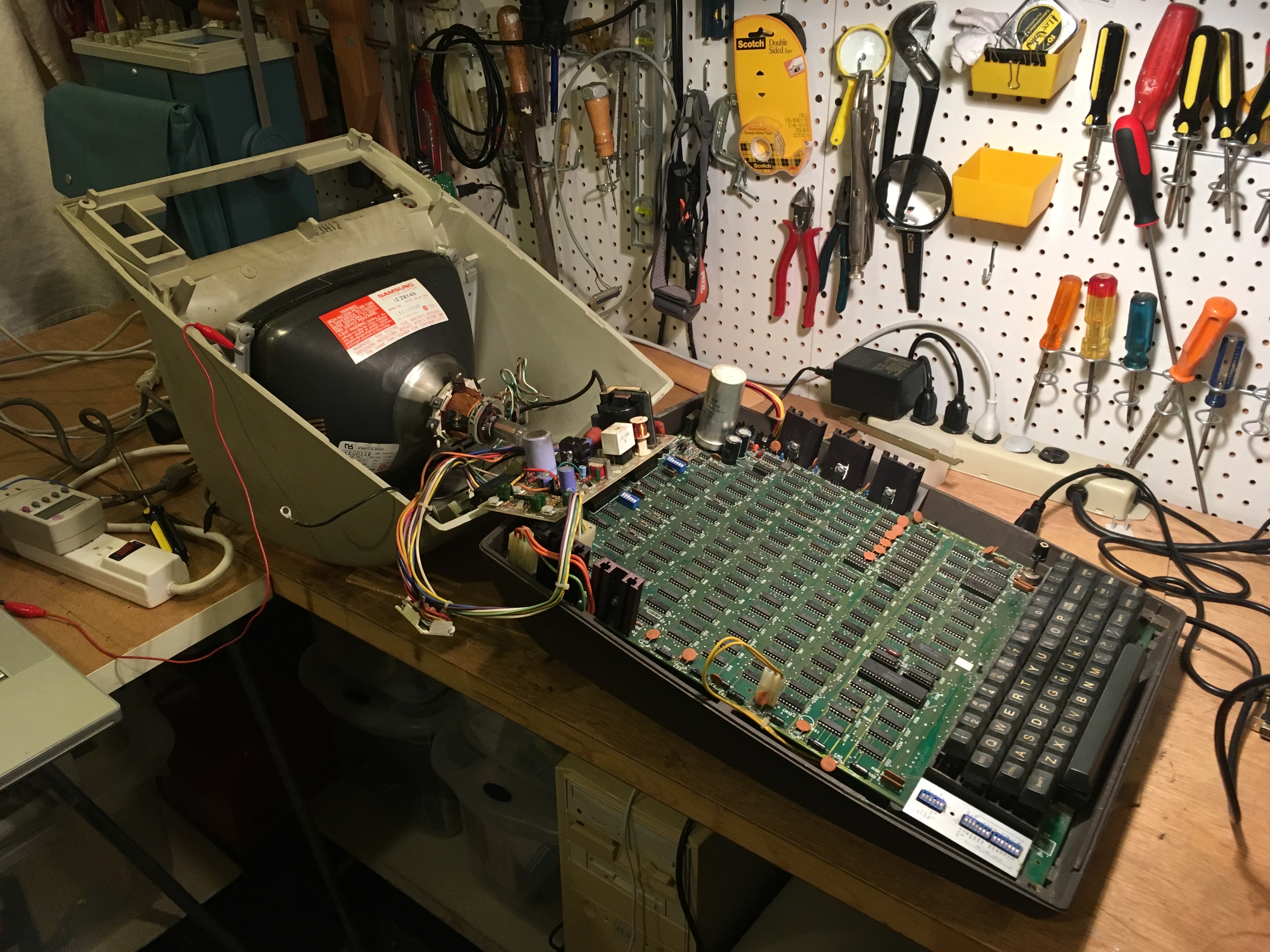 I checked the three power regulators and a few connectors: VR4 - 0.8V VR5 - 5.02V VR6 - 5.1V Q3 - 14V VR1 - 15.3V Pin 10 (gnd) - 11 (15V) on J7 measured at 15.3V Pin 2 (gnd) pin 3 (-12V) on 1602 (U??) measured at -11.8V With the exception of VR4, these showed reasonable power to the analog board, so I was surprised not to at least have the CRT charging up. After replacing VR4, the measured voltage was 5.0V, but this didn't change things. I verified with my scope that there was no output to HDRIVE, which was stuck low. I traced the signal back to to U50 pin 11, which was at 2V. This is the CC3 (character counter clock that generates HSYNC), so this 74LS161, a binary counter, wasn't counting. The dot counter, U33, also wasn't working. I desoldered U50 and U33 and soldered in sockets. With new 74LS161 installed, I powered up and… got a beep! I powered down, hooked up the monitor and powered up again to find an image now that HSYNC was being generated. It was a relief. From the looks of the heavily corroded flyback transformer, I wasn't sure if I would get the CRT working or not. The image was compressed and skewed heavily to the right, but it was something. There was no function from the keyboard, or evidence of any other function. The screen was garbled. 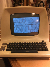 Video logic With video being generated, I could now set to work in earnest. First up was fixing the position of the video image. Rotating the ring magnets on the CRT lined up the image in the center, although it remained compressed vertically. Moving the two magnets relative to one another fixed the vertical position, too. (to be continued...) 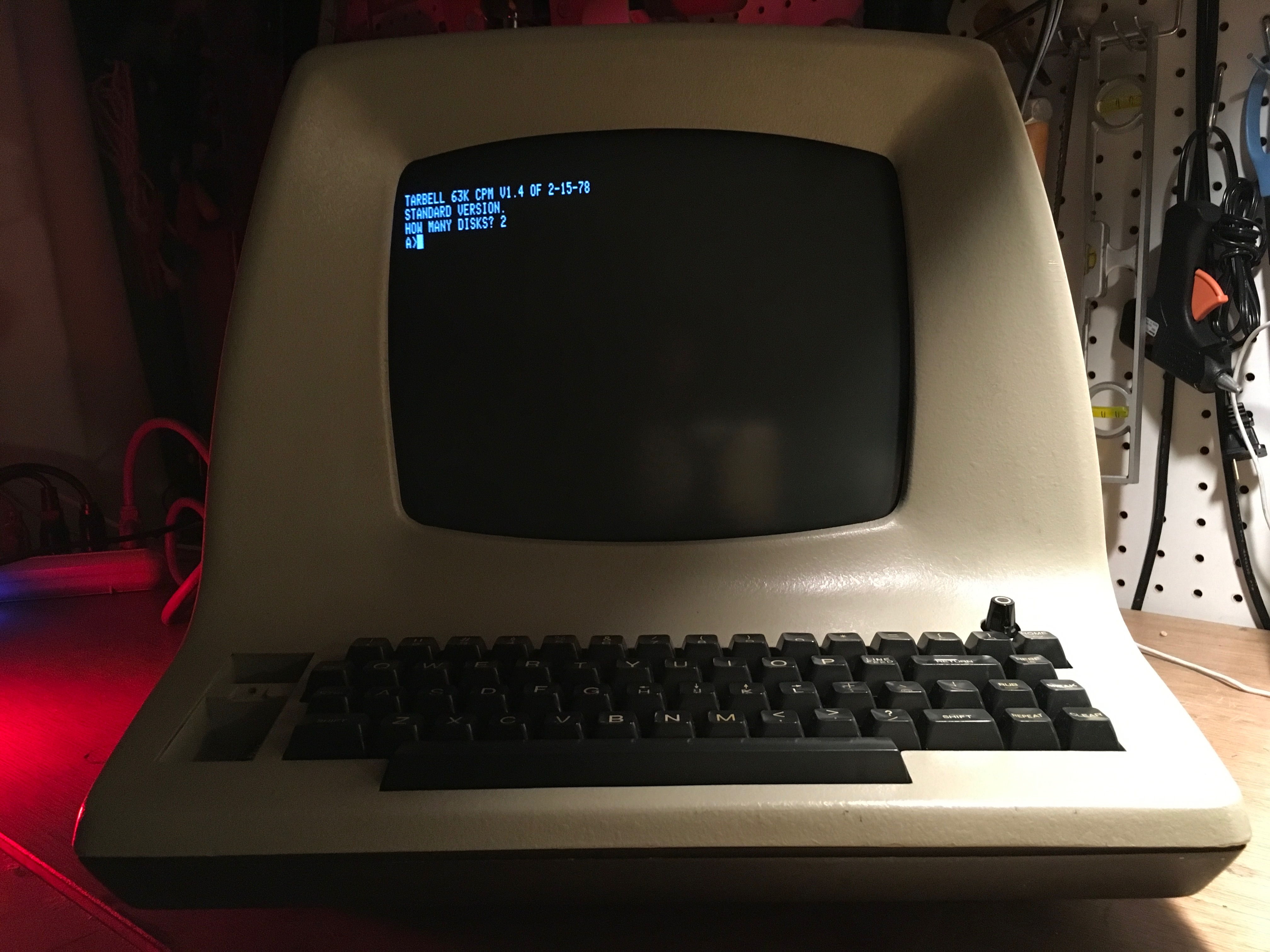 |