Disk drives for the IMSAIMy next project was to get a disk system up and running with the IMSAI. By the not infrequent means of paying good money for other's e-waste, a Tarbell 1011A single density drive controller and two Thinker Toys (rebadged Shugart 800) 8" disk drives came into my possession. I was looking at my toughest retrolab challenge to date with an unknown drive controller and drives. It ended up being an exercise in steady, slow moves and a lot of luck that my components weren't junk. It did take a good six months to work out some of the kinks, though. I started off by documenting the state of the controller card and the drives. Each had many modifications, and understanding those changes would be essential to getting them up and running in my machine. First up was the disk drive controller. The Tarbell controller is based on the Western Digital FD1771 controller chip. 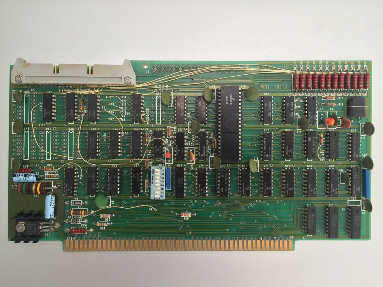 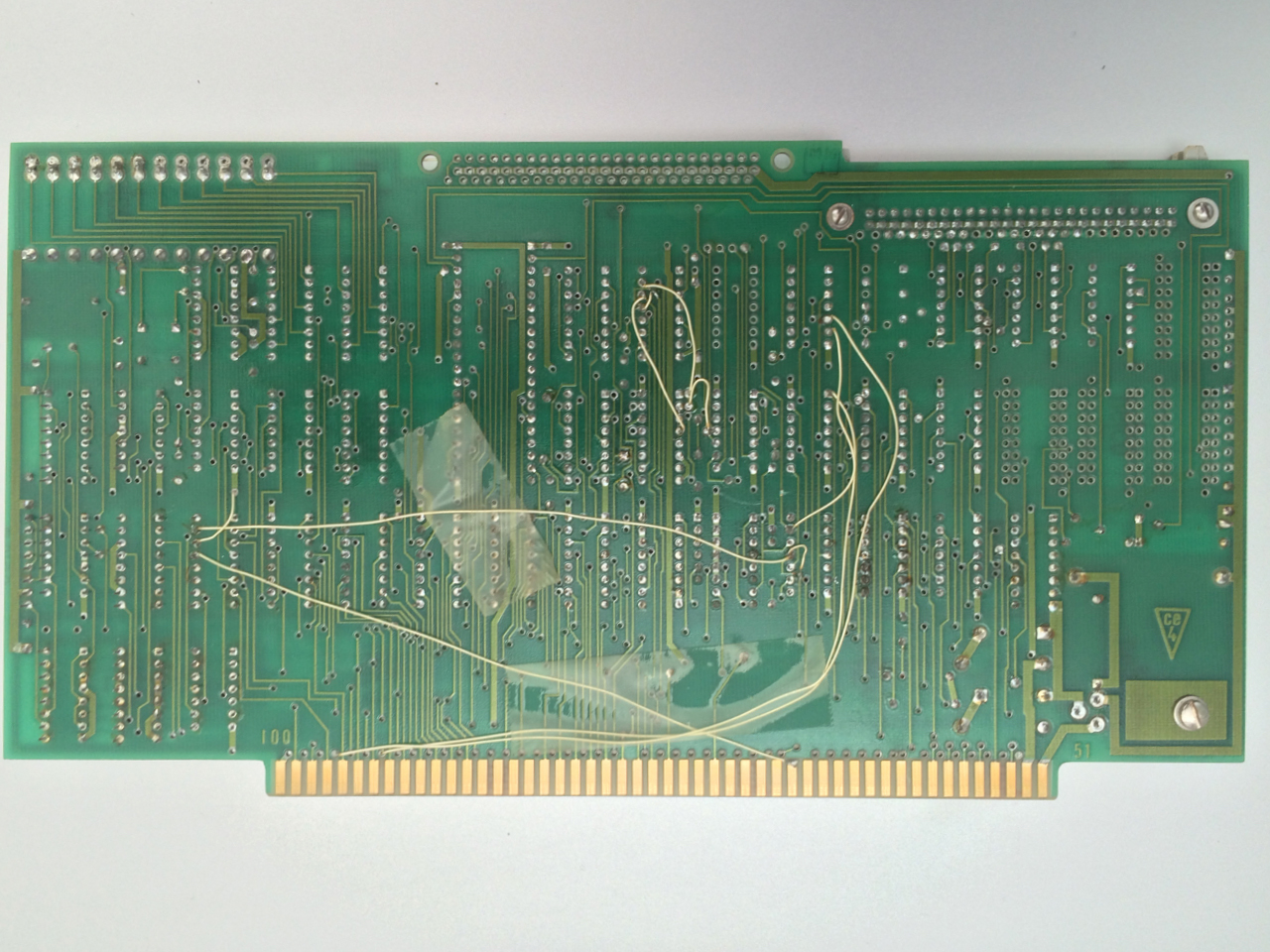 The modifications to this board frightened me a bit, but it turns out that the number of jumpers is standard for the Tarbell and are used to accommodate a wide array of drive types with different capabilities. The board documentation gives modification instructions for each drive manufacturer, including the Shugart 800's. The changes on the back of the board were mostly for operation with a Z-80 processor, and are also documented in the manual. Most of the jumpers on the front side were good as they were, while those on the rear were removed to operate with my 8080 card. This included several trace repairs, which were cut as part of the Z-80 mods. Below is a table from p 7-8-1 in the manual that summarizes the board changes for Z80 operation and those that I've noted "as received," as well as the action taken.
These are the jumper settings documented for the Shugart and those on the board as received. There are only two jumpers to remove—they were for the TG43 signal, which the Shugart generates on its own.
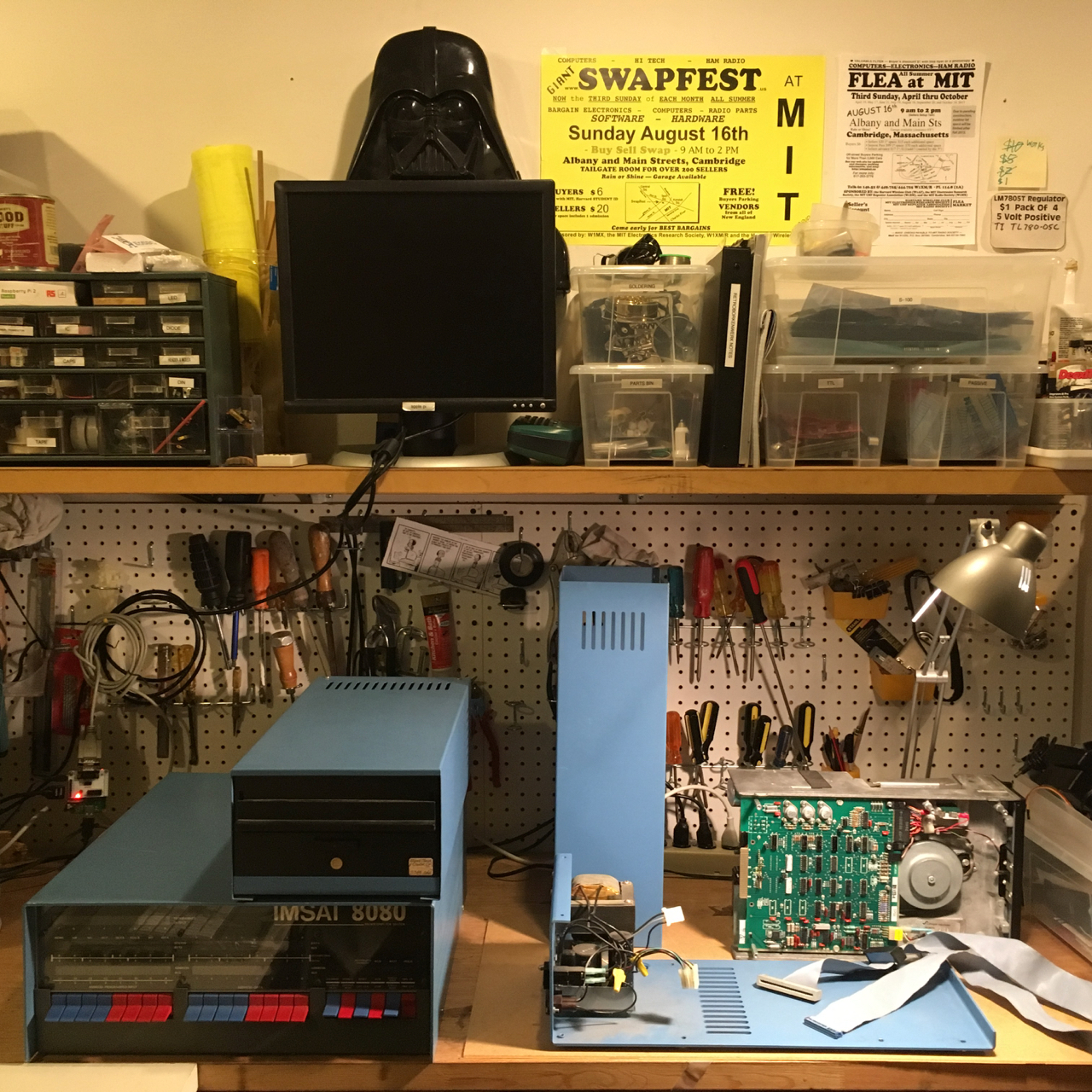 George Morrow's company Thinker Toys produced the Discus drive system in the late 70's. The drives are stock full height, single-sided Shugart 800's, each in a sheet metal case with its own linear power supply, power switch, and fuse. When they're switched on, the drive spindle spins continuously by an ac motor. The head is driven by a DC stepper motor. Disk wear is reduced by loading and unloading the read / write head. A felt pad loads the head against the disk by a solenoid activated cantilever. Each drive power supply generates the +5, -5, and +24VDC required by the drive electronics. In my case, the PSU produces -9V and the drives are jumpered for operation between -7 and -16VDC (jumper L). The drives are fantastically electromechanical and so much larger and more complex than the 5 1/4 inch (Apple) drives I used as a kid. I disassembled first 8" disk drive and brought the drive power supply up on a variac with the control board disconnected and measured outputs after about an hour or so. I also powered "disk 1" up. This one was in a bit worse shape. The PSU was unplugged from the motor and control board when I opened it. There are several missing screws, so it was looser in its frame. There was more debris on the bottom and some signs of rodent activity, although it looks like it may have gotten in through the vent. Interestingly, the second drive is a model 800-1 (not 800-2 like the other). The control board does not have solder mask. The disk drive assembly does not have the same serial number as the label on the Thinker Toys case, so it must have been replaced or exchanged at some point. That could explain why the power was disconnected. It also took me a little while to realize that all but one of the jumper wires to the R/W head (J1) had been cut, which I had to resolder. The Tarbell controller documentation provides the settings for the Shugart drive control board. A summary of the control board settings as received and necessary changes are below.
The ac motor on both drives ran, the drives could clamp and spin disks, and so the belts looked good as well. I built a cable to connect the 50 pin slot connector of the drive to the berg connector of the Tarbell controller and set off to do the first tests documented in the Tarbell controller manual with with "disk 0": Type 1 commands all worked, confirming master reset test (a machine reset causes the head to move to track 0), step in / step out test (actuate the stepper motor), and seek test (move the head to a specific track). The "head load" type 2 command also checked out. These tests are performed with short programs entered through the front panel. Here's a picture of the first drive under initial tests: 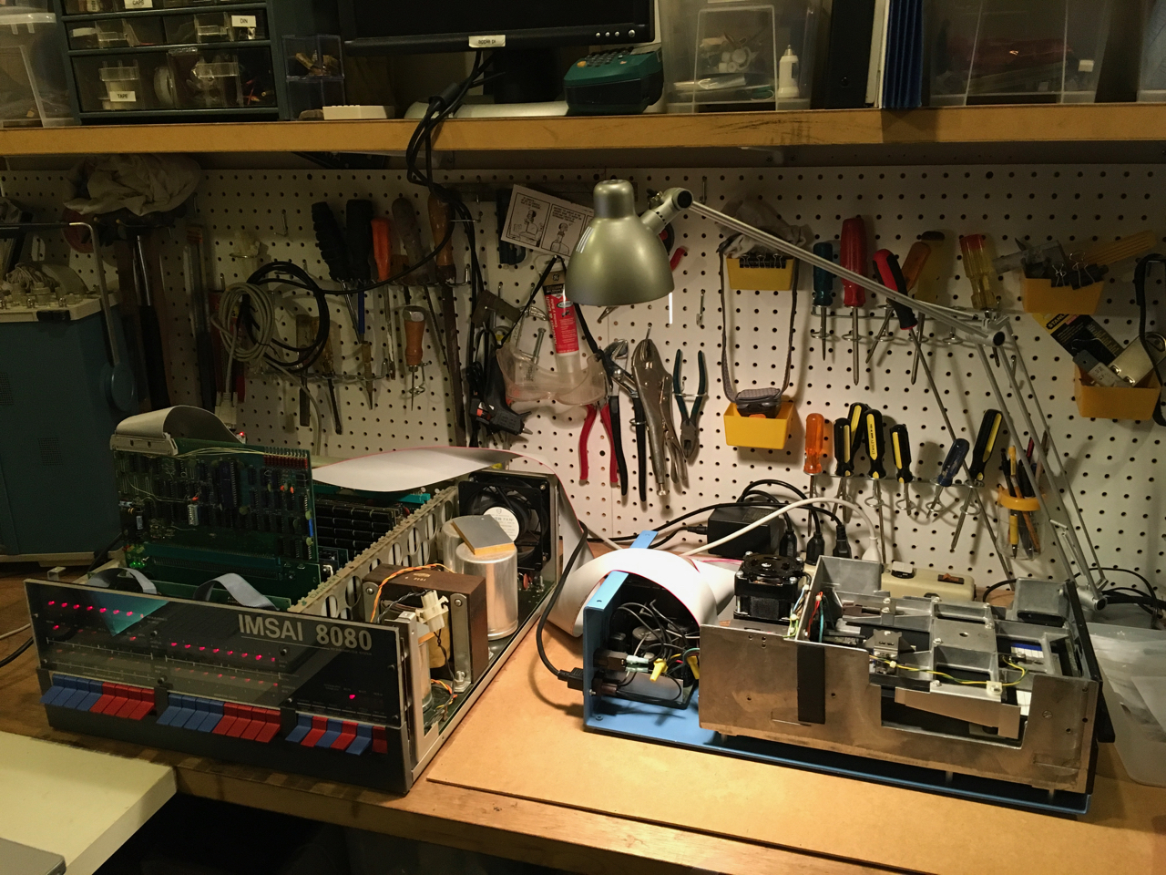 So far, so good. At least basic commands were making it to the drive, which was responding appropriately. Next up was to see if I could get CP/M running. The most straightforward path would be to write an archived boot disk to media then try to boot it with the IMSAI. That would require getting the drive to work with my disk imaging computer and a CP/M BIOS modified for the Tarbell controller and my I/O. Page listing - "Subpage Listing" | |||||||||||||||||||||||||||||||||||||||||||||||||||||||||||||||||||||||||||||||||||||||||||||||||||||||||||||||||||||||||||||||||||||||||||||||||||||||||||||||||||||||||||||||||||||||||||||||||||||||||||||||||||||||||||||||||||||||||||||||||||||||||||||||||||||||||||||||||||||||||||||||||||||||||||||||||||||||||||||||||||||||||||||||||||||||||||||||||||||||||||||||||||||||||||||||||||||||||||||||||||||||||||||||||||||||||||||||||||||||||||||||||||||||||||||||||||||||||||||||||||||||||||||||||||||||||||||||||||||||||||||||||||||||||||||||||||||||||||||||||||||||||||||||||||||||||||||||||||||||||||||||||||||||||||||||||||||||||||
IMSAI 8080 >