I disassembled the machine. The first order of business was replacing the sheared off fuse block. The fuse holder is a Littel model 342 with 3/16" straight quick connect ("Q.C.") terminals and a fluted knob. Littel still makes the part (P/N 342 038), so sourcing that was easy. I could order 2.5A or 4A "slo-blo" fuses, while the manual specifies 3A. I went for the 2.5A initially while I got things up and running. Next, I brought the power supply up slowly on a variac while monitoring the 12V output. At 50% the output was 8.5V on the 12V line and the fan started running slowly. At 100%, the 12V line held steady at 11.87V and I measured -11.89 V white/yellow to white (should be -12+/-0.6V) and +5.05V green / white (should be 5+/-0.25V.) Things looked pretty good, so I connected it to the PC board after the normal check-out for shorts across caps. No response. The 5V power fell to about 1V on the motherboard. In hindsight, it seems obvious that Q1 (a TIP41 NPN) had ceased functioning properly on the power supply regulator board. Without a load, the second transistor in the Darlington pair, Q2 (a 2N2222 NPN TO-18 with a slide-on heat fin attachment) could provide sufficient current in the circuit, but would easily fail once a load was applied. Which it did. Replacing these alone may have fixed the problem, but my initial repair was faulty. I'm uncertain why. Q2 burned out again and the voltage dropped to -100mV on the 5V line when I connected it to the PC board. I was worried that I may have caused damage to the PC board components. Eventually, I also replaced the MC1458P op amp that makes up the regulator circuit and the power supply held fine. I first tested it with a 10 Ohm 5W resistor, after which I was confident enough to reconnect everything. Finally, the 5V held steady at 5.02V measured at the J1 connector and 4.86V at the personality module and keyboard. During the repair I also dabbed Q1 and Q2 with fresh heat sink compound to help reduce their thermal load. I still wasn't getting video from the PC board, though. I tested the AMD C8080 in my IMSAI and at least that ran fine.   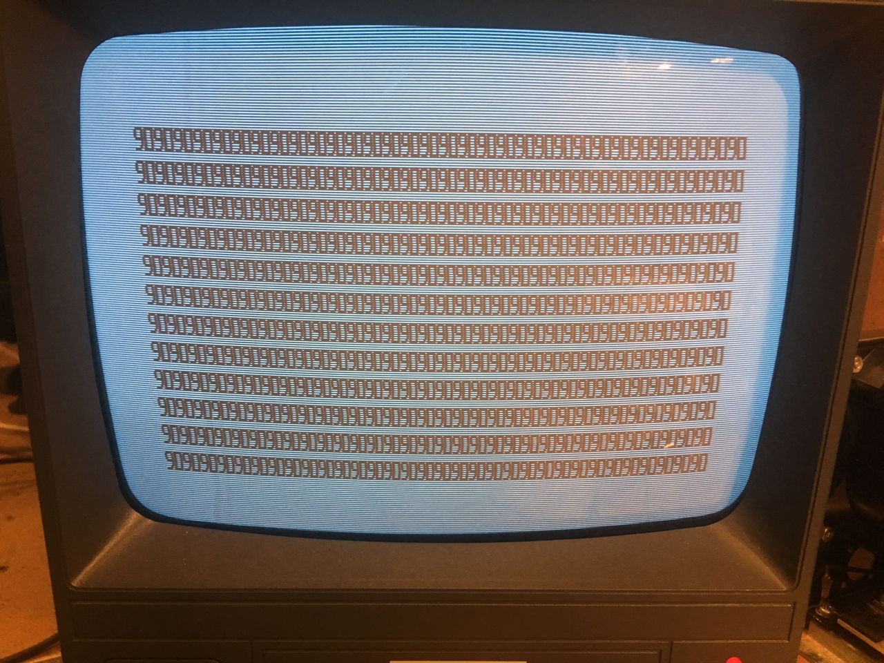 It was a solid sign that the basics of the Sol-20 were sound. The processor and video subsystem worked and it was fetching and storing data to the onboard memory. I installed the personality module and was greeted with the SOLOS prompt! Too easy! Indeed, after a minute or so, the display reverted back to the test pattern. Creating a RST with S1-1 got the cursor back a few times, not always for that long, but then it would go back again to the test pattern. I powered down the machine and plugged the keyboard circuit board in. There was no video initially and the keyboard lights were on. I pressed what may have been shift lock and that started the cursor and repeated "7" characters. No other response would register. I turned the machine off and on again, but there was no response from keyboard. The shift lock light came on momentarily, but then it went off. Glitchy, right?  I needed to solve the repeating character problem. I moved parts around the keyboard PCB and replaced several TTL components one at a time, focusing at last on the key switch detect circuit. By exchanging both U17 and U21, I found that the ICs behaved identically in the U17 slot, but not in the U21 slot. These chips drive the capacitive pads on the circuit board and they should be pulled up to 5V when inactive by resistor packs RX1 and RX3. RX1 looked normal, but I measured unusually high resistances on RX3, about 100kOhm from the pins to the 5V input on the board. Was the resistor pack dead? Measuring directly across it gave normal resistances of 2.2kOhm. I traced the 5V line back and this is when I discovered that the 5V trace was corroded through near the "R26" label. Meanwhile, the machine went to "90" pattern again, and I couldn't get it back with any number of resets. By this time, I was just grounding the NP jumper to reset the machine, rather than using the S1-1 dip switch. I installed a jumper over the corroded point on the 5V line of the keyboard. This got the keyboard LEDs responsive with "key presses"—caps lock, shift lock, and "local." Now it was time to see if I could get the ROM back. I fiddled around with the personality module, but it looked like the addressing was fine. Scoping the address lines, I could see that the machine was running through all addresses. The Sol-20 startup isn't as simple as jumping to the ROM code at 0xC000. Instead, during power on or reset, the !PHANTOM line is driven low, disabling the RAM while also causing the ROM to respond to address 0x0000. On a hunch, I focused on U65, U66, U77, U78, which are data bus multiplexers for the internal bus. If a bus conflict occurred here, data from the PROMs couldn't reach the processor and the keyboard wouldn't function either. They are also suspiciously close to the J3 keyboard jumper socket, and once or twice inserting or removing the keyboard seemed to trip the test pattern. Scoping the ICs showed some abnormal voltages, so I pulled each of these and cleaned the (heavily tarnished) pins. I also pulled U64 and U63 and cleaned these as well as the sockets. What do you know? The machine powered right up to the SOLOS prompt. I powered it off, inserted the keyboard into J3, and rebooted. SOLOS came up. I could type with my fingers directly on the keyboard PCB pads. The machine was finally working. Here's an image showing a "DU C000 C0EF" command in SOLOS to dump the first 240 bytes of the ROM. 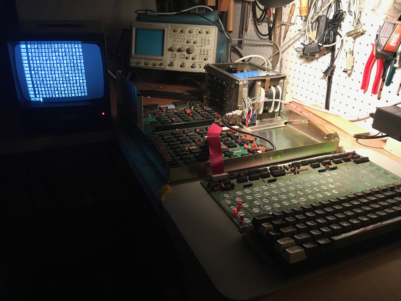 This wasn't the first time that I ran into problems with corrosion on ICs, especially with Texas Instruments chips. They seem to suffer from some sort of galvanic corrosion more than any other manufacturer from the mid- to late-70's. I've systematically cleaned all of the TI chips on the keyboard and motherboard. My summary here doesn't really capture the degree of uncertainty I experienced throughout this work. The most frustrating aspect was the computer's intermittent behavior. Several resets seemed to work until they didn't. Then, resetting while using a logic probe to test pin 1 on U24 (!phantom) went straight to the SOLOS ROM several times—until it didn't. I experienced these and other false starts and wrong turns, but eventually converged on a solution. I'm sure I'm in for more surprises, but next up would be repairing the mechanisms of the Keytronics capacitive keyboard. Over the next few months, the machine started generating "ghost keypresses" from time to time. An erratic series of characters would show up at the prompt, sometimes the screen would clear spontaneously, and other times, it would lock up. The keyboard seemed to work fine, except "upper case" tended to take multiple keypresses to work. Other times, the machine wouldn't start at all. Removing the keyboard from the case helped. Sitting on the table, it would often work fine. I suspected a few things: the keyboard PCB could be flexing in the case. It is fairly rigid, but only supported on the ends. Could there be unusual grounding issues? Removing the screws holding the keyboard in seemed to help, but then the ghost keypresses resumed. It got worse over time. Before delving deeper, I decided to check out the trace repair I made earlier. It could be a bad solder joint on the wire I installed. I made a second repair by removing the first, then etching out the corroded trace fully. Things seem to be holding up now. |
PTCO Sol-20 >