I/O for the IMSAI
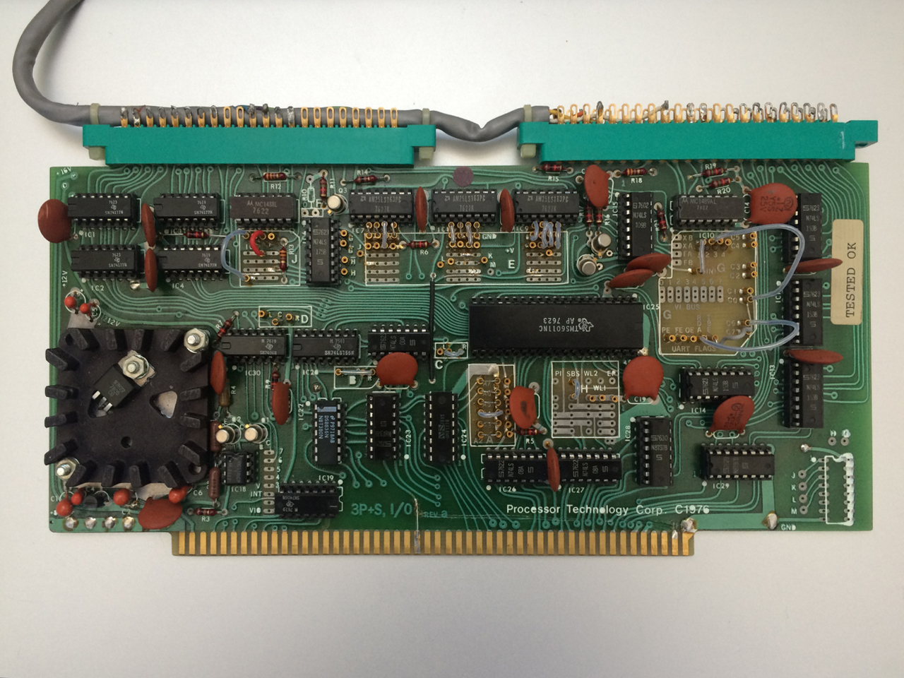
The 1976 Processor Technology Corporation 3P+S Input / Output Module Revision A.
I love the trace layout on this board. You can just imagine Ingram and Marsh (and Felsenstein) in their Berkeley garage laying out the pads and traces by hand. It has a distinctive, human touch.
Here's what I know about the board so far:
- None of the tantalum caps are shorted
- The 7805 produces 5V
- The trace to pin 24 (ø2 clock) is cut and jumped to pin 49 (clock).
- I couldn't make sense of the jumper settings on the card!
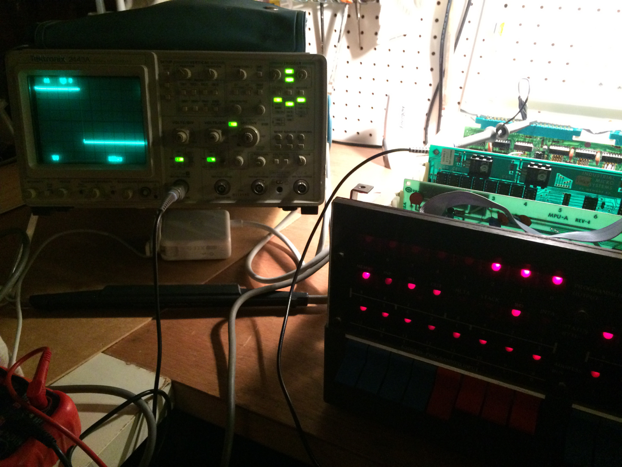
After setting up the card for port 00-03 and RS-232 output, I made it to here:
A short program sends the active user input port switches to port 01 (and the front panel display). I can see the bits on the scope. However, there seemed to be memory corruption issues with the 3P+S card installed, especially at $0000 and $0001. I removed the jumper to pin 49 and repaired the trace to pin 24. It looks as though things have improved.
Alas, a short while later, the card stopped sending any output and the memory became flakey again on all pages at addresses 00 and 01. It seems that the card is creating a bus conflict. I suspect it is IC 22, a DM8836 (N8T380N) "Quad Bus Receiver" (quad NOR) that controls the 3P+S DI lines. When the CPU signals an I/O port read (SINP) simultaneous with a data bus read (P DBIN) through IC 22 along with the jumpered I/O addresses on the address lines, the N8T97 buffers driving the DI lines are pulled out of a high impedance state. Most of the output pins on IC 22 are floating around 1.8-2.3, and as a result, the card's buffers are kept active on the DI lines. Unfortunately, this chip is incompatible with 7400 equivalents, so it will require a special order.
Update: replacement Signetics N8T380N received, installed, and card function restored. The IMSAI was last seen sending ASCII to a Raspberry Pi's GPIO at /dev/ttyAMA0.
Currently, I have the 3P+S jumper settings configured as follows:
TBE (transmitter buffer empty) to D7
RDA (receiver data available) to D6
EIA 1 IN (received data) to UART. Connect jumper between 1 (just below "IC10") and Rin.
EIA 2 IN (carrier detect) to DI0 (data in bus) - jumper between 2 and C0
OE, FE and PE no jumpers installed
GGGV GVVV VVVV
G = ground (row 1), V = +5V (row 2)
Alternatively, the baud rate can be set to 300 baud:
Area H - word length and stop bits (8N1)
SBS to ground - stop bit select. One stop bit if low.
Since WLS1 and WLS2 (word length select) are not connected they are held high. This gives 8 bits per character.
Since PI (parity inhibit) is not connected and thus held high, it gives NO PARITY.
EIA 1 OUT to UART. This is pin M on the J1 slot.
All jumpered to ground, which means I/O ports 0x00-0x03
Area B (order of response of four I/O channels)
Left Jumpered to Right, which means channel order is c,d,a,b
0 0 C 0000 0000 - status channel
0 1 D 0000 0001 - serial, handles data to / from UART
Right jumpered to center, which means hardware UART setup (not programmable setup)
Center to Right, which means that current loop is disabled
Area F (peripheral control driver)
The RS-232 output is on pin M of J1, the input is on pin K of J2, and the signal ground is pin 11 on J1.
Serial loader
Now that the serial card is up and running, I'm using the following loader to transfer program binaries from a Raspberry Pi to 0000H on the IMSAI. The 20-byte loader program is toggled in at $1C00, the last 1k in my 8K of RAM. The program outputs the current byte being written to the programmed output LEDs.
1 ;; ================================================
2 ;; LOADER_1.asm
3 ;;
4 ;; Load code at 0000H from 3P+S serial card
5 ;; card is configured for I/O on port 01
6 ;; status byte on port 00. Status bit C7 is
7 ;; TBE and status bit C6 is RDA.
8 ;;
9 ;; asm8080 cross-assembler
10 ;; asm8080 XX.asm -P -l
11 ;; ================================================
12
13
14 00 00 STATUS EQU 0
15 00 01 PORT1 EQU 1
16 00 80 TBE EQU 080H ; transmitter buffer empty bit is D7
17 00 40 RDA EQU 040H ; receiver data avail bit is D6
18 00 FF PANEL EQU 0FFH
19
20 1C 00 ORG 1C00H ; put in top 1K
21
22 10 1C00 11 00 00 LXI D,0000H
23 10 1C03 DB 00 LISTEN: IN STATUS ; check for incoming data
24 7 1C05 E6 40 ANI RDA ; using RDA bit
25 10 1C07 CA 03 1C JZ LISTEN ; no data, keep listening
26 10 1C0A DB 01 IN PORT1 ; read serial input
27 7 1C0C 12 STAX D ; store in memory
28 5 1C0D 13 INX D ; next memory location
29 4 1C0E 2F CMA ; output current byte
30 10 1C0F D3 FF OUT PANEL ; to front panel LEDs
31 10 1C11 C3 03 1C JMP LISTEN
32 END
*******************************************************************************
Symbols table
*******************************************************************************
Names Types Values
----- ----- ------
STATUS EQU 00000h
PORT1 EQU 00001h
TBE EQU 00080h
RDA EQU 00040h
PANEL EQU 000FFh
LISTEN Label 01C03h
The Pi is set up with an RS-232 shield that runs off the GPIO /dev/ttyAMA0 pins. At some point, I must have disabled the console output on /dev/ttyAMA0 in /etc/inittab. Once /dev/ttyAMA0 is configured with stty, the loader is started and the binary transferred:
cat PROGRAM.bin > /dev/ttyAMA0
I transferred Steve Dompier's MUSIC OF A SORT program and data in about five seconds at 300 baud. The 212 byte 8080 binary is attached below. Whew, what a relief. Toggling in 212 bytes stinks!
It seems that I'm on track in recreating the 1970's early microcomputing experience. Here's a reflection from the era taken from the February, 1976 issue of Dr. Dobbs: "The goal of about ninety percent of small systems owners appears to be to get their systems up and running with some kind of I/O and then procure enough memory to support a higher level language."
Page listing - "IMSAI 8080 pages"