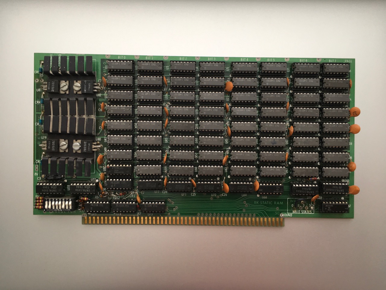
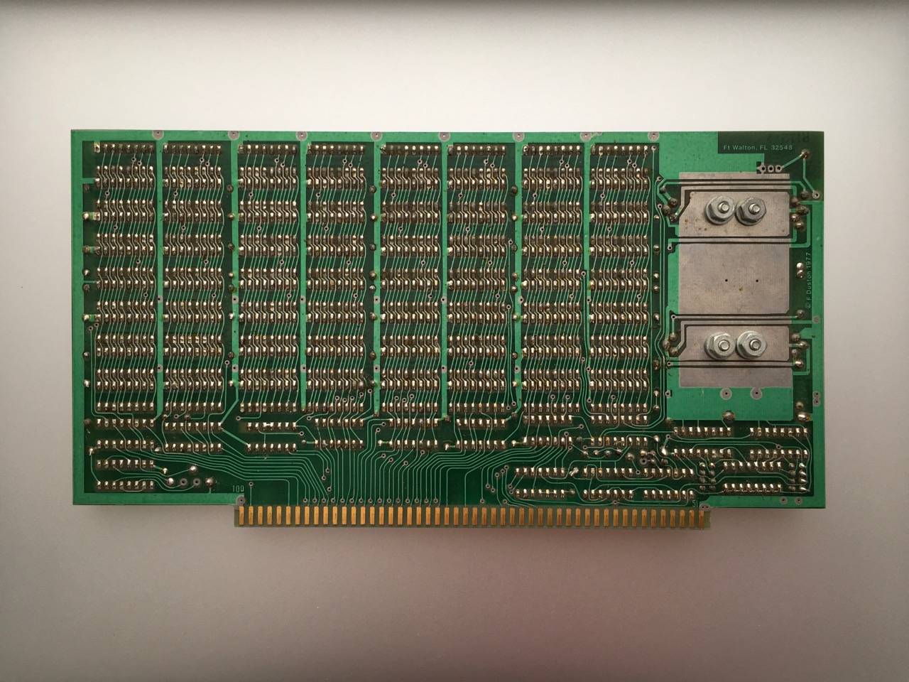
Tinkering, Tweaks, and Repairs Since getting the IMSAI running, I've made a number of tweaks, including how I interface to it (a Raspberry Pi and an ADM-3A terminal) and topping off the memory to 64K. The machine has generally behaved well. Disk drive 1 has had intermittent problems, but I believe that I've tracked it down to the buggy disk drive door switch. I added two 8K SRAM memory boards to max out the machine: an "F Duston" board and Vector Graphics 8K Static RAM Rev. 1. F Duston 8K RAM board F Duston (c) 1977 Ft. Walton, FL 32548 Very little information exists on the Duston boards. I can't locate a manual or schematic, but it appears to be the same or similar to the Ithaca Intersystems (Ithaca Audio) 8K SRAM board. “Forrest Duston” is typed at the end of Ithaca board's directions—presumably he was the designer and author. The addressing scheme for the Ithaca board is identical, but the published PCB layout is different. The schematics and addressing information allowed me to get the board up and running. Like many earlier boards I've worked on, the memory checked out with deposits and examines from the front panel. I addressed the board at $C000 and made a 55K CP/M disk, but it wouldn't boot. However, I could get the machine to boot with the Duston board addressed at $2000 and IMS board at $C000. By transferring images of disks to my Raspberry Pi, I was able to identify some sticky bits on the board. In all, three 2102 chips appeared to be bad: U25, U33, and U63. Replacing these got the board working with CP/M. A few days later bit 4 stuck high across the entire address space. Thinking it was unlikely that I had a whole row of RAM go bad, I took a look at U69, a 74LS04 that connects the outputs of the bit 4 RAM chips to S100 pin 38 (D04). It looked like U69 pin 8 was floating, and a quick swap with a replacement fixed the sticky bit. The Duston board's flakey memory shares a common element with other memory boards: Sometimes memory that appears fine by deposits and examines using the front panel, or with memory test programs, fails under CP/M. I'm beginning to suspect it is a problem with the disk drive controller DMA writing and reading directly to memory with the CPU in a wait state. Perhaps the timing is tighter under DMA? The "WORM21.ASM" memory test program that can be found on various CP/M archives notes (at least with Z-80's) that the M1 cycle has stricter access timing than normal reads and writes. As an interesting side-note, Forrest Duston shows up later in Palatine, IL. Processor Tech's April, 1978 issue of Solus News describes a "10-slot daughter board" by Duston for the Sol-20 and gives the Illinois address. Around the same time, in Ward Christensen and Randy Suess's article about their first BBS in Byte Vol 3, #11, 1978 they note the additional memory they purchased: "We are now running an 8 K Vector Graphic memory board and two 8 K byte boards designed by Forrest Duston (a local hobbyist and design engineer), which were donated by Lloyd Smith and Bill Bassett of DMA Inc." Vector Graphic 8K STATIC RAM board  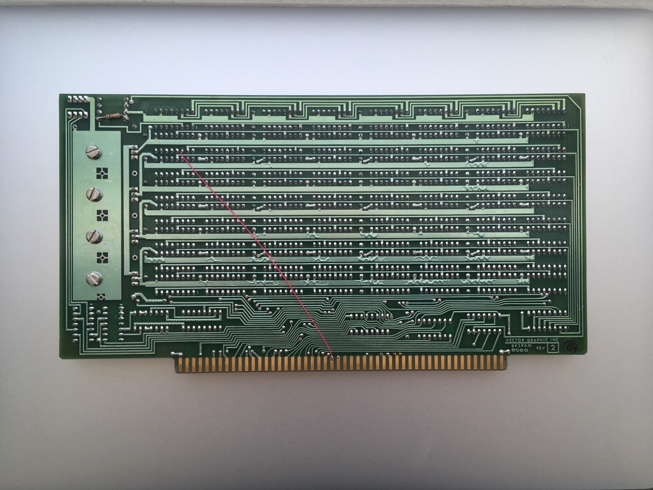 Funny enough, the last memory board I added was also used in Christensen and Suess's BBS system: the Vector Graphic 8K STATIC RAM card. This one is labeled Rev. 1 and arrived in extraordinarily good and clean shape. Since the manual is available online, it was easy enough to address at the final 8K in my system at $D000 using the three DIP switches. There was one bodge wire soldered onto the back that connected the S-100 bus pin 74 (!PHOLD) to the R/W pin 3 of the 2102 at B0 (bit 0, second 1K). I removed the wire. While the board fired up fine and all of the 5V regulators seemed to be in good shape, I couldn't get any response out of the card. The front panel was reading something, with occasional $FF's reported back in the memory space, but I couldn't write to the card at all. Troubleshooting was stymied by the fact that the schematics weren't published in the manual—a very rare lack of information in the hobbyist era. To get the board working, I started by cleaning pins on the buffer and control logic ICs. Despite the good condition of the board, many of these chips showed a heavy, white oxide buildup, and were actually quite hard to pull from their sockets. Cleaning didn't improve anything, though. So I started mussing about on the addressing chips and buffers with a scope to see if anything looked out of the ordinary. Then, luckily one evening I discovered the board's schematic was published in the appendix of Dave Bursky's book, "S-100 Bus Handbook". I happened to be looking at it when it dawned on me that the memory protect switch, the fourth in the DIP package that controls the board addressing, should actually be closed. The open switch disconnects MWRITE (pin 68) and pulls it high. Sure enough, closing the switch got the board working flawlessly. I ran a MEMTEST on it without detecting any errors and later rolled up a 63K CP/M. Understanding CP/M sizing With the last two boards installed, the IMSAI has 64K total installed RAM. CP/M needs to be resized to use this additional memory. The default CP/M installation is for a 16K machine. A transient utility program, MOVCPM.COM, can be used to relocate the code to a higher address space. The basic process is to run MOVCPM, then use DDT to "patch" the CP/M code with your own boot loader ("CBOOT.ASM") and custom BIOS ("CBIOS.ASM") that are specific to your hardware (serial cards, disk drive interfaces, video display technology, etc.) My target was a 63K CP/M. Why not 64K? Well, CP/M v1.4 assumes that the CBIOS is 512 bytes. Hence, in a "default" 64K machine, CP/M would occupy between CBASE (the start of the CCP) at $E900 and the top of memory, with FBASE (the start of BDOS) at $F100. Under these circumstances, BIOS would begin at $FE00 and end at $FFFF. I'm not sure exactly how any CP/M CBIOS fit into 512 bytes, but in order to accommodate something larger, CP/M must be relocated to a lower point in memory—1K lower is sufficient because the BIOS size is ultimately limited by the total storage of the first two disk tracks. This is why CP/M is sized for 63K and not 64K with the Tarbell CBIOS. Total storage on the first two tracks of a CP/M disk (26 sectors / track, 128bytes / sector for the single density IBM 3740 8" disk format that was being used), after subtracting 128 bytes for the boot loader routine, gives a maximum 6528 bytes ($1980) for CP/M CCP, BDOS, and BIOS. Sectors 18-21 on track 01 correspond to the default BIOS allocation, and sectors 22-26 would be unused. Based on the number of sectors, the maximum a CBIOS size is nine sectors worth of data, or 1152 bytes. Moving CP/M down by 1K, BIOS then begins at $FA00 and ends at $FE80. That leaves 128 unused bytes at the top of memory, although uninitialized storage references, like track tables and error counts, could be specified in that area. Currently, the Tarbell CBIOS goes to $FE09 in my implementation, with 19 bytes of variables and tables stored above this final instruction. I have about 119 bytes to spare—just nine bytes under one sector's worth of data. The "bias" in the case of 63K CP/M is $BC00 (not $C000 as it would be for 64K). The CCP would start at $E500 and BDOS at $ED00, and of course, BIOS at $FA00. Bias, in CP/M parlance, is the offset from the CCP address of $2900 in the 16K default implementation of CP/M. Get all of that? Whew! Page listing - "Subpage Listing" |
IMSAI 8080 >