OlivettiTE-318
This document describes the restoration and operation of an Olivetti series TE-300 teleprinter. Work on the teleprinter began in August 2018. The Olivetti was restored to operation in mid-December 2018, but my work continued through December 2019 (and beyond) with improvements and additional repairs.
CHI È: OLIVETTI TE-318 TELESCRIVENTE
The exercise of restoring a teleprinter has two principal aims: The first is to understand and operate some of the tools available to users at the dawn of the microcomputer era. Teleprinters were early peripheral devices for microcomputer hobbyists. Already widely used in central computer facilities, they provided a user with console input (keyboard), output (printed type), and program storage (paper tape) long before CRTs, tape recorders, and later, floppy disk and hard drives became common (and affordable). Thus, we have the well-known story of Paul Allen flying to Albuquerque with the paper tape code for BASIC that he and Bill Gates wrote to test on Ed Robert's MITS Altair 8800.
The second aim is to study the effects of time on the materials that were used to build the teleprinter. Early microcomputers and their associated peripherals and equipment present interesting challenges for conservation and restoration as they age. Many of the problems faced restoring the Olivetti stemmed from degrading plastics, rubbers, and lubricants, not to mention failing electrical components and the occasional metal corrosion. Preserving the material culture of the late 20th century will depend on our ability to undertsand, and possibly stabilize or mitigate, such material degradation. Material failures?
Teleprinters -- a brief overview
Teleprinters (also: teletypewriters, teletypes, or ttys), especially those in use during the mid-to-late 20th century, represent a transition period of technologies during the formative years of the computer and information ages. The genesis of the teleprinter is set firmly in the era of telegraphy. A teleprinter is essentially a machine that automates sending and receiving telegraphic codes, eliminating the need for operators to be trained to send messages, or to always be present to monitor for incoming messages. With a teleprinter, messages could be automatically received and printed. The process became ubiquitous to a point that teletypes once rattled in news bureaus 24/7 across the country, steadily churning out wire reports. Teleprinters were also central to aviation, industry, military, and government communications throughout much of the 20th century. NASA even considered equipping the Apollo command module with an onboard teleprinter to free the crew from having to write down a flood of messages, especially instructions for the guidance computer [Michael Collins, Carrying the Fire, 40th Anniversary Ed., Farrar, Straus and Giroux, New York, 2009, p. 105].
At the end of the teleprinter era, information would be sent by digital signals over local networks, telephone lines, and later, the internet. In contrast to our digital devices, the design and hardware of a teleprinter very much reflect its telegraphy roots. Basically, the only electrical component in a teleprinter, besides the main motor driving its operation, is an electromagnet. (Well, there are two switches that control the direction of signaling and transmission and a few electrical filters.) This magnet converts on and off states of current (that is, an open or closed circuit) into mechanical action, just as a telegraph operator would open or close a DC circuit to send a signal, resulting in a distant electromagnet opening (resting) or closing (marking or working) in response. [Aside: Current flow] The remainder of the teleprinter transports and acts on these signals by purely mechanical conveyances---converting a signal of sequential pulses to type or patterns of holes in paper through shafts, clutches, levers, gears, springs, bars, vanes, slides, cams, bails, and more. It's a wildly complicated (and noisy) contraption.
The mechaics may be complex, but the design of a teleprinter is a fairly simple affair. It's made of just two principal parts: an emitter and a receiver. There is no immediate internal connection between the two; sending and receiving functions are independent. The emitter consists of the keyboard or punch tape reader. These send their output through a serializer, which mechanically opens and closes the loop circuit. In order to print what is typed (in local mode, for instance) the same electrical signal is passed back to the receiver, beginning with the action of an electromagnet, which connects to a parallelizer. The parallelizer converts the serial signal to a parallel one by positioning code bars, which in turn ultimately control the output to a print head or reperforator. A fun trick is to feed the paper tape from the reperforator into the tape reader to create a loop of infinite punching---or one that lasts at least until the tape runs out. For those who think in digital electronics, the parallelizer and seralizer are simply mechanical shift registers.
Before the advent of magnetic mass storage, punch tape was a useful means for storing programs and reading them back into a computer. But why were teleprinters equipped with tape perforators in the first place? One answer is that it enabled faster and less error-prone communications. An operator would first type a message off-line in local mode to generate a punched version on tape. The transmission could then proceed by feeding the tape into the reader. The message would be sent faster than an operator could type, and any errors could be corrected beforehand. This practice minimized the active (and costly) time each machine needed to spend on the communications line. A receiving perforforator (reperforator) was also used to forward messages. The tape produced a copy that could be retransmitted.
Some of the fun in all of this is to find out how the old telegraphic system ended up making its mark on the more modern era of digital communications. A teleprinter in an inactive state holds the circuit in a "marking" mode---our digital "1". This system provides a communication channel between two stations that is verifiably connected and not broken by error or fault. A stop bit is a "rest", which triggers the electromagnet off and starts the process of reading the subsequent bits that will arrive shortly thereafter. Hence, "0" is the start bit of a modern serial signal, followed by more ones and zeros.
Physical description of the Olivetti
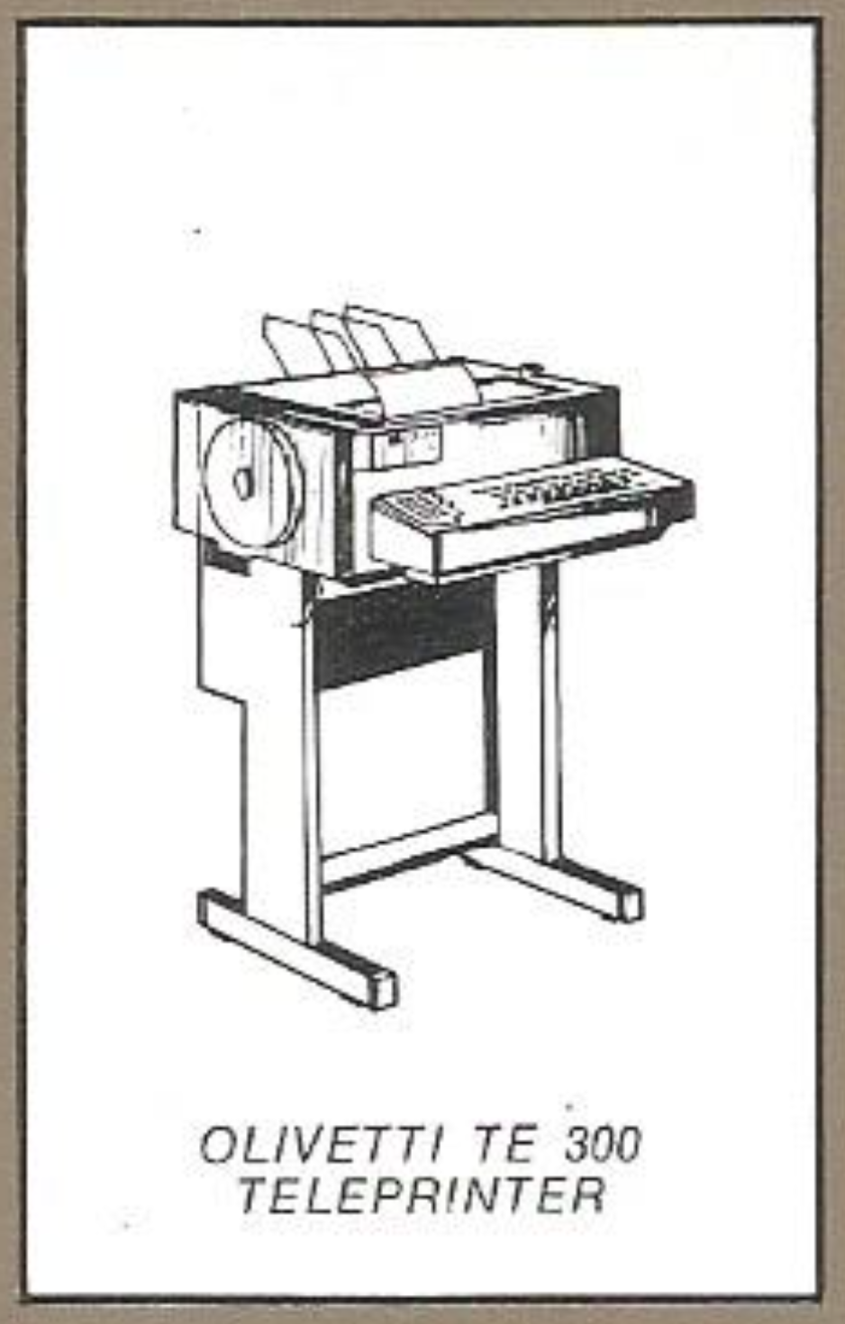
The Olivetti Te-318 is a teleprinter that is made up of a keyboard and printer, paper tape punch (reperforator), and paper tape reader. The machine is similar to other teleprinters, such as the more familiar and far more ubiquitous (in the US) Teletype Corporation model 33 ASR. [Aside: Teletype Corporation] Like all teleprinter equipment, the Olivetti relies on a current loop to send and receive information, but this machine is equipped with a communications interface -- a telegraphic power supply unit -- that accepts a standard RS-232 signal. A metal stand acts as a base and bus (via the rack) for interconnecting the power and communcations lines. Three other accessories included with the Olivetti are the reperforator tape holder, a chad box, and a paper roll mechanism that feeds paper from the back. The whole thing weighs about 120 lbs.
Olivetti components
The teleprinter components are as identified by their part and serial number tags:
- Teleprinter - olivetti Te 318, no 539648
- Tape punch - (reperforator) - olivetti Pe 308, no 409556
- Tape reader - olivetti Se 308, no 409876
- Telegraphic power supply unit - olivetti Telescriventi, Ivrea, No 426720 (Also referred to as the "Connection box")
- Rack - olivetti Telescriventi - Ivrea, No 411942
The Te-318 is a model in the Olivetti Te-300 series and is preceded by two Olivetti teleprinter lines that date back to the 1920's: The T1 and T2. The Te-300 series was manufactured between 1968 and 1975. The 300-series is a family of machines that work on 5-bit (Baudot) codes or 8-bit (ASCII). The Baudot model number in the Te-300 series is the Te-315. Teleprinters were also sold without the reperforator or tape reader (TL-300), and sometimes without the keyboard as a receive-only equipment. The 5-bit Te-300 series machine in a receive-only configuration has the model number Re-315. Given the date codes on several internal parts, the machine was likely manufactured between mid-to-late 1971.
The teleprinter sits on the metal stand. The punch and reader are built into the teleprinter, but can be removed as whole units. The power supply unit attaches to the right side of the machine by three metal tabs, which fit into slots, and a locking screw. The plastic reperforator paper tape feed and chad boxes hang on the left side. A paper roll feeder attaches to the back and there is a metal paper guide that attaches to the top. The teleprinter top opens by two swinging doors to access the paper and paper tape feed.
Inside the stand is the "rack", which acts as sort of a bus for making connections between the telegraphic power supply unit, teleprinter, and the outside world. Two cords connect the power supply unit to the rack: a power cable (7-pin DIN style) and an "interface cord." The power cable carries the mains to the unit as well as the teleprinter. The rack front swings down to access the cables and plugs. There is a linear power supply in the power supply unit for the electronic interface. A separate step-up transformer in the teleprinter unit powers the machine's motor. The interface cable has a Cannon-style 50-pin female D-sub connector in 3 rows (DD-50). The teleprinter also connects to the rack, but with three cords: a telegraphic cord, which carries the telegraphic signals (in this case, to the electromagnet and from the serializer), another 50-pin "services cord," which carries additional electrical signals from switches and sensors (in paricular from the functions unit), and another power cord. Finally, the rack has an DB-25, RS-232 connector and a plug for the main power cable. Two of the Cannon plugs on the rack have date codes "7122" and "7106," so those parts date to the first half of 1971.
There are a few other part numbers throughout the teleprinter, presumably to identify different installed options. The print carriage, the part of the printer head with four character wheels, is labeled "832". This is possibly to distinguish 5-bit baudot and 8-bit ASCII operation. The functions unit, which decodes certain received characters from the code bars, such as CR, LF, and BELL, is "F 813". The keyboard is marked with a label "863". Each of these labels is a white paper tag. Just above the motor on the main unit is another tag, "813".
ASCII-63
The Olivetti teleprinter sends and receives ASCII-63---the original 1963 specification of the ASCII character codes. The alphabet of ASCII-63 consists of upper case letters only and with no underscore, carat, or vertical bar characters---these appear as left arrow and up arrows when printed. It sends 7-bit code with even parity and 2 stop bits (7E2) at 110 baud. (Teleprinters are sometimes set up to send 1.5 stop bits, presumably at slower baud rates with 5-bit operation.) Each character is preceded by one start bit, so the machine processes 10 characters per second. According to service manuals, the baud rate is adjustable and can run slower or faster. The 5-bit version runs at 50, 75, or 100 baud, so the equivalent rates for 8-bit operation are about 75, 110, and 150. The print platten accepts standard 9.5-inch by 11-inch continuous form feed paper.
Keyboard and controls
The machine is equipped with a QWERTY keyboard, a numeric keypad, and several additional keys: SHIFT and SHIFT-LOCK, which really act as CONTROL to send ASCII control codes, but in some cases also a normal shift to send symbols; a repeat key, which repeats the last character; an ENQ key that triggers the automatic reply mechanism; a NULL key, LINE FEED key, and CARRIAGE RETURN key (yes, you will have to manually type CRLF, but you could also type LFCR); and a DEL key, which sends 0x7F (0xFF with parity) and prints a backspace arrow. No, the print head will not move backwards, other than to return to the first position with a carriage return. Finally, there is a shorter bar to the right of the space bar that clears the keyboard when it locks. Locking occurs when two keyboard keys are pressed simultaneously.
There are several other user controls. The console of the power supply unit has four buttons: ON, C, BRK, and L, to turn the machine on, send a clear, send a break, and to put the machine in LOCAL mode. C and BRK are momentary switches. These, and three internal switches for power (including an automatic power-down mechanism), are the only electrical switches on the teleprinter. The rest---the keyboard and function keys like reperforator and tape reader controls--are mechanical. There are also five indicator lamps on the power unit: ON, MR / RS, LOCAL, and CD. The punch has switches to start and stop the mechanism, feed tape (punching the last character received) and a backspace. The latter allows one to move the tape back one and over-punch it with DEL to effectively blank out a mistake in a tape. The reader has start, stop, and single advance buttons, as well as a release switch to load tape.
Paper tape reader and punch
The Olivetti is equipped with the Se 308 tape reader and Pe 308 reperforator. The paper tape follows the "ECMA-10 standard for data interchange on punched tape" published on Nov. 30, 1965. The paper tape is 25.40mm (1.000 inch) wide. Each bit is recorded as a "track," starting from track 1 (right-most, at the reference edge) and ending at track 8 (left most) as the tape is being fed out of the machine. Feed holes are placed between track 3 and 4. The 1965 ECMA-10 standard also stipulates that the the maximum outer diameter of a coil of punched tape is 190 mm, but this was increased to 200mm in the 2nd edition ECMA-10 standard published July 1970. Unfortunately, standard 8 inch diameter paper tape rolls are about 13mm too wide for the Olivetti. Because it uses the ECMA standard, the orientation of the Olivetti paper tape is the mirror of teleprinters that follow the ANSI X 3.6 1965 standard (Known as USA R1973, Perforated Tape Code for Information Interchange), like the Teletype ASR-33.
Print head
The print head design uses four vertically oriented wheels that move together horizontally and rotate together. There are sixteen glyphs per wheel corresponding to the 64 printable characters. (The space character is normally suppressed, but the machine will print an open circle if the suppression mechanism is disabled.) Through the print head mechanics, the code bars set the horizontal position to line up one the four wheels to strike the paper and rotate the wheels to pick one of the sixteen characters on it.
The Olivetti typeface is similar to the "techno" typeface found on at least one Lettera 32 typewriter model, but a few numbers are different. The number "3" on the teleprinter type ends with a delicate, thin stroke at a slant -- beak-like -- not the squared form of the Lettera's number. The same holds for the "5" and "9", but other numbers (2, 4, 7, and 8) appear identical to techno. The parentheses also have a noticeably sharp end.

Machine provenance
I purchased the Olivetti from Chris C. in August 2018. Chris was selling their family residence of about 60 years in northern New Jersey and was clearing out the house's large storage space on the second floor. The Olivetti was originally purchased by Chris' brother, who, just out of high school in the mid-1970's, was an early and eager microcomputer enthusiast. The brother attended the first Atlantic City Computer Show and later computer shows in Philadelphia. He ended up with an IMSAI 8080 around that time---coincidentally, one of the machines in my collection that I wanted to use with the Olivetti.
I wish I had more details about why Chris' brother chose the Olivetti over more common teleprinters like the ASR-33, but I suspect that he got a good deal. The TE-300 series was replaced by the TE-400 series in 1975, so older models may have been cheaper and therefore more appealing to microcomputer hobbyists. I found an example of one other hobbyist using the Te-300 in the US in an article published in the May, 1980 issue of BYTE by Joel Swank ("KIMDOS: Using Your KIM-1 with a Percom Floppy-Disk Drive," p. 44.) A photo shows a Te-318 used as a hard-copy terminal. Chris' brother drove with his father to Boston to buy the machine; no one in metro NYC area sold them. His destination may have been the American Used Computer Corporation of Boston, MA. A search turns up advertisements the company pubslihed for the Te-318 in several 1979 and 1980 issues of Computerworld.
The Olivetti spent the better part of 40 years in basically the attic of the house. From the exterior, it seemed to be in reasonable shape, but I'm sure heat and humidty took their toll. I noted some corrosion on the stand, but little else other than on the paper guides. It was dirty with a crust of heat-fused dust, and later I would find some typical signs of mouse activity, but luckily, no big, stomach-churning nests or infestations. Initially, I didn't have the chad box or the paper roll assembly. Chris later found these parts and got them to me. He also gave me a stack of fliers and other ephemera from those early computer shows. Chris' brother had collected information on SWTPC, Cromemco, MITS, and others, as well as the first few issues of Microsystems Magazine. Maybe he shook hands with many of the early microcomputer pioneers? Chris was pretty sure that he met Stan Veit, the fouder of New York's first computer store, Computer Mart, and later the Computer Shopper. I also got a few other interesting bits of early microcomputer gear, including speech synthesizer (Computalker) and speech recognition (Speechlab) S-100 boards for the IMSAI. The other real finds, though, were two Olivetti serivce manuals and the operator manual. That was fortunate. While they had been battered and were missing a few pages, without these, I doubt that I could have restored the Olivetti. They provided essential insights into the operation of this bewildering device.
Restoration
Eventually, I hope to document my restoration of the Olivetti. It's a fascinating machine. I've had a lot of fun (and some frustration) getting it working. Ultimately, it was a formidable puzzle. I've also improved my Italian (still negligible), lost a little hearing, and even bled some along the way.


State of the machine as received
When I picked up the Olivetti, it had already been disassembled in order to move it down from its second floor storage area. The stand, teleprinter unit, and (telegraphic) power supply unit were detached. The machine was dusty and had spots of corrosion, especially on the stand. It wasn't in the worst condition, but it hadn't been kept in a climate-controlled space, either. There was a good coating of grime on the keyboard and tape reader, and a thick, matted dust, on many of the other parts.
I got it home and into the workshop. I inspected the machine and started trying to understand the major parts. I took apart the power supply unit first to examine its state. The PCB inside and associated electronics (including two large transformers, several capacitors, and a circuit largely comprised of transistors and relays) looked fine. It had a network of bodge wires on the back of the PCB, but the components looked sound. The date codes on a few of the transitors were 1970 and 1971.
Next, I removed the main cover from the machine. Regrettably, the sound-proofing foam that once lined the case had stiffened into a light, brittle mass [photos]. The foam disintegrated with the slightest touch. It had covered the internals with a thick grime. The powder-like remains had stuck to every greased part, making a thick coating. Machine grease was also packed throughout the mechanics. I'm not sure what it was like originally. It was now pungent, very yellow, and in places brown to black.
I performed a careful inspection of the machine before trying to start it and cleaned what I could of the foam and its debris. The electonics of the power supply / connection box appeared sound. One fuse of the three fuses had corroded and no longer made contact.
Getting started -- inital observations
I attached all of the cabling and initially powered up the teleprinter on a Variac, my usual approach with machines that haven't been turned on for years or decades. The control lights begin to glow on the power supply console, then I heard a snap. The thermal (?) breaker (red, labeled 0.4) on the back of electrical breakout box had opened. With power on through the Variac, pressing this engaged power to the motor, but it quickly shut off again. I noted some play in the belts and gears and things loosen up a bit. I proceeded to rock the belts and gears to work things free. Each time I restarted the motor (which shut off by the breaker) it advanced and sped up a little further. Since Variac was limiting to 110V, I plugged directly into a (breakered) power switch. The motor ran a bit faster and eventually it came up to speed. The tape punch was running, and I seemed to turn this off. The punch mechanism did not advance and the reader mechanism appeared to be frozen, too. It would turn out that most of these observations were due to the gummed up grease in the machine, which had frozen a many of the mechanics. The punch, in particular, needed to be lubricated eventually, but that was far down the road.
Key presses on the keyboard registered with some sort of action, but the carriage did not advance. Every once in a while the carriage moved to the right. No action was observed on the printer. The carriage return and paper advance switch on the right worked. Some keypresses put the machine into a "chatter". In hindsight, this was the dysfunctioning parallelizer. Since I was still learning about the overall construction of the teleprinter, I had to guess that the transmitter and receiver were decoupled. Indeed, this explains why many keys wouldn't advance the carriage---the machine simply wasn't receiving the right characters.
Major repairs
I documented my repairs in notes and an electronic notebook, and through several threads on Twitter. (Now archived!) Here are the main repairs in the order they were made.


- Serializer---the serializer was restored to operation, enabling the teleprinter to send characters from the keyboard and tape reader. Mostly, the code block was gummed up by degraded grease.


- Parallelizer---In order to print or punch, the teleprinter must be able to receive and demodulate signals from the electromagnet through the parallelizer. The parallelizer had failed due to broken levers in the copy frame. The images below show the bottom half of the copy frame. The two remaining intact levers were measured to make 3D printed replacements. This was the most significant and difficult repair. The reassembled copy frame is shown in the last image.


Once the parallelizer was fixed, I could punch tape using the reperforator, but the print head was still inoperable. - Print head---like the serializer, the print head mechanism was frozen. This repair required removing, lubricating, and working to unjam the gears and other mechanisms that take the code bar settings and print a character. It's a fascinating and complex component.


- Print shaft coupler---two welded pins broke and caused the failure of the coupler that transfered the rotational motion of the main print shaft to the print head, likely because the print head was frozen. The pins were reattached using a copious amount of reinforced epoxy. Ultimately, it would be better to re-weld the pins or fabricate an alternative coupler.


- Stroke bar---the frozen print head had also caused severe damage to the stroke bar, all but rendering it inoperable. The stroke bar is the code bar that causes the print head to print a character. The piece is plastic, and the frozen print head chipped it away. I repaired it using a long 2mm rod and reinforced epoxy.


- Motor circuit---the motor capacitor and spark filter failed. The spark filter short-circuited, resulting in faster operation (150 baud) than expected (110 baud.) Once I understood how to remove the motor assembly, removing and replacing the spark filter was straightforward. Surprisingly, I found NOS filters were available from an Italian supplier.


- Telegraphic power supply---I reverse engineered the telegraphic power supply circuit board and other electrical connections of the machine. The telegraphic power supply unit converts the teleprinter's current loop to a standard (110 baud) RS-232 signal. I replaced several burned out indicator lamps. Thankfully, all of the unobtainium germanium transistors seem to be working.


- Hour counter mechanism---The machine should power off after running idle for some time. The hour counter mechanism relies on a gear that disintegrated. With the help of Rue Mohr (@RueNahcMohr) we found the size and pitch from the remaining fragment and Rue was able to generate an STL file. I had a replacement manufactured and the counter is now running. The auto-stop mechanism appears to be disabled, though.


A good number of the repairs above may have been the result of frozen mechanisms, especially the copy frame of the parallelizer and the print head. If I were to start over, I would carefully inspect these areas and attemped to get them lubricated and moving before powering the teleprinter. This insight may serve as a useful starting point for others restoring Olivetti machines.
Modifications and other work
- Functions unit---Beneath the code bars is the functions unit. This reads and processes special codes, such as the
BELLcharacter,CR,LF, codes that remotely start and stop the tape punch (DC2,DC4), and theENQcode (known as Who Is?, or in Italian, Chi È?). I removed a linkage in order to prevent0x05(the ASCII code for the autoreply mechanism) from suppressing the reperforator.


Retrolab notes
The documentation at the bottom of this page link includes detailed notes I made during my work. Although maintenance and repairs continue to the present, I printed and hand bound my existing notes in August 2020.


Twitter repair threads
All of the Twitter repair threads in one convenient place!
Fun with the Olivetti Te-318


My projects with the teleprinter include:
- Using it as the console for an IMSAI 8080, Raspberry Pi, and MacBook
- Tweeting from it with
oysttyer(twitter handle @OlivettiTTY) - Punching tweets on the reperforator
- Creating a tweet-punching Twitter appliance so others can send messages to paper tape
- Punching lovely patterns and letters
- Creating ASCII-63 art and ASCII Mandelbrot renderings
- Adapting Art1 for 80 column format and printing compositions
- Running a pen plotter from the punch tape reader
- Wirelessly connecting to remote machines with the wifi232 modem
- Editing files and code with
ed - Simply figuring out how it works and keeping it working
Orphaned Se-305
For the cost of shipping, I obtained an orphaned Se-305 paper tape reader. The Se-305 is the five-bit Baudot sister to the Se-308 8-bit reader on my Olivetti Te-318. The Se-305 cleaned up well and can (manually) process 5-bit tape. Having it helped me understand the modular construction of the teleprinter accessories. It bolts onto the frame and is driven by a gear that couples to the main print shaft. Five levers connect to rods in the machine that drive the code bars.


Documentation
The following Olivetti teleprinter documentation either came with my teleprinter or was provided by others in the community (*).
| File | Type | Size | Description |
|---|---|---|---|
| Te_318_Operator_guide.pdf | 34M | Te318 Operator manual | |
| Te_318_Adjustments.pdf | 34M | Te318-specific adjustments | |
| Te_315_Diagnostic_Guide.pdf | 99M | Te315 service manual (mostly complete) | |
| Te_315_ISPT.pdf | 28M | Italian Post Office Te315 course book* | |
| Te_315_Operator_guide.pdf | 3M | Te315 Operator manual* | |
| Servizio_Tecnico_T01_M02.pdf | 34M | Telegraph and motor circuit diagram | |
| Olivetti_907_49_2_1.pdf | 100M | Olivetti TE315 Theory and Operation* | |
| Personal notes and sketches made during the restoration. | |||
| Olivetti_TE_300_vol_1.pdf | 170M | Notes and sketches 1 | |
| Olivetti_TE_300_vol_2.pdf | 272M | Notes and sketches 2 | |
| Olivetti_TE_300_vol_3.pdf | 173M | Notes and sketches 3 | |
| Olivetti_TE_300_vol_4.pdf | 14M | Notes and sketches 4 | |
| Olivetti_Log_web.pdf | 421K | Typed notes | |
| OlivettiPSU_10212020.pdf | 610K | Telegraphic Power Supply Unit schematic | |
| Copyframe_Lever_3x16.stl | STL | 326K | Parallelizer replacement copyframe levers |
| o-gear-r1-s.stl | STL | 357K | Replacement hour counter gear (Courtesy Rue Mohr) |